
Eureka
For R&D, Eureka makes reading and utilizing patents & technical documents easy.
Eureka AIR
Designed for self-driven R&D workflows. Generate viable solutions, solve complex R&D challenges, empower your innovation with AI.

Eureka Materials
Designed for material experts only. Revolutionize your material R&D, from search, analyze, to developing new materials.

TechResearch
Generate reliable direction feasibility study reports for your R&D in just a few steps.

TechSeek
Discover and master advanced knowledge NOW. Basics, ideas, possibilities, all at once.

TechMind
As an expert in R&D Theories, TechMind can generates customized viable solutions instantly.

TechRisk
Analyze your overall solution with one click, know your potential R&D risks in advance.

TechMonitor
Get weekly tech updates, stay abreast of the latest tech innovations and key insights.
Catalyst Included in Hollow Porous Capsule and Method for Producing the Same
- Summary
- Abstract
- Description
- Claims
- Application Information
AI Technical Summary
Benefits of technology
Problems solved by technology
Method used
Image

Examples
embodiment 1
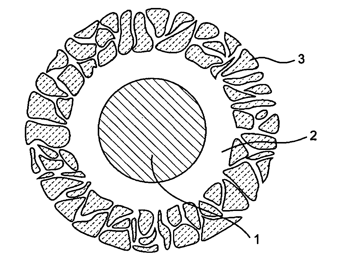
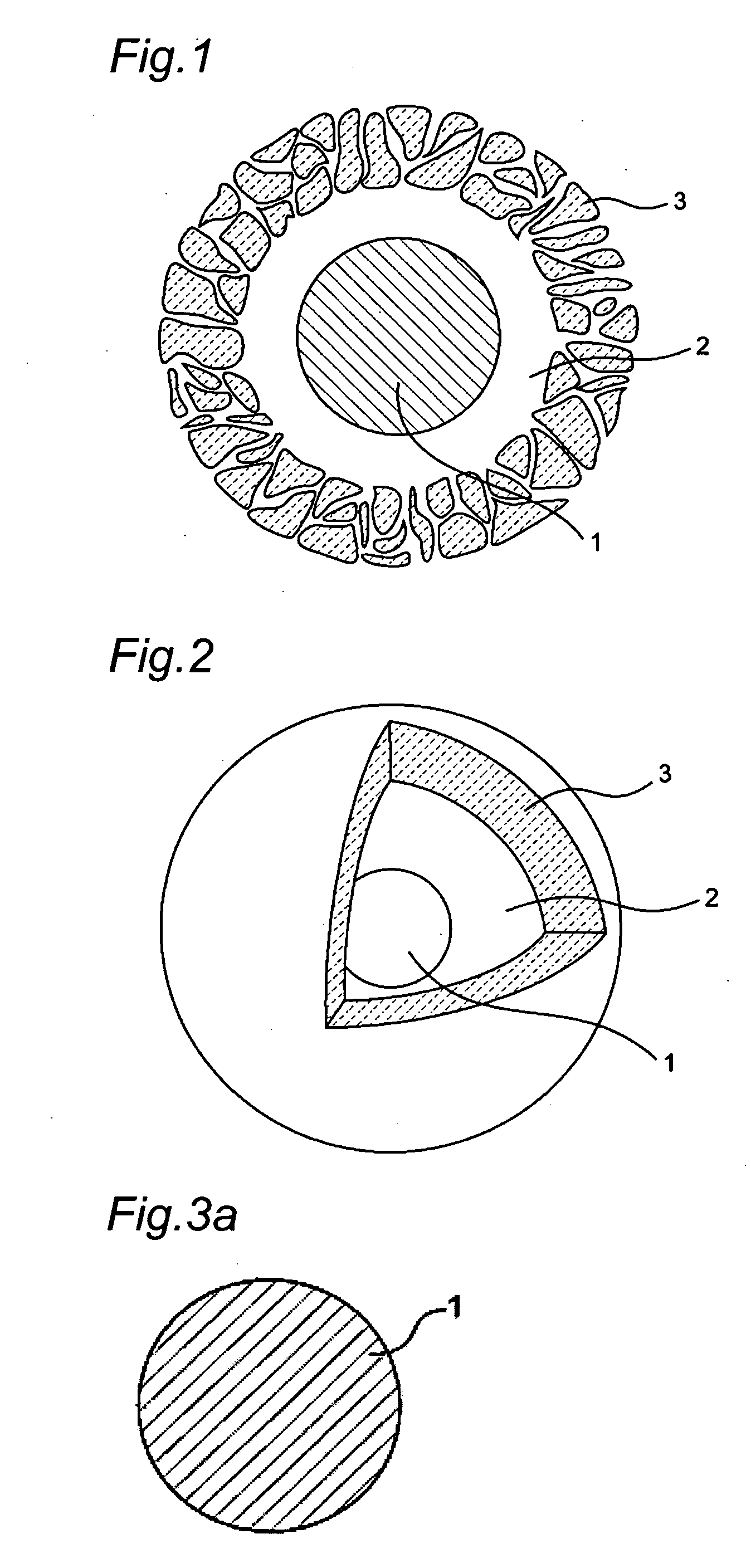
[0049]As shown in FIG. 1, the catalyst according to the embodiment of the present invention includes a core portion 1 containing catalyst nano-particles and a porous layer 3 formed so as to cover over the core portion 1, and a hollow layer 2 exists between the core portion 1 and the porous layer 3.
[0050]Since the porous layer 3 has a porous structure, a solution to be catalyzed penetrates into the porous layer 3 from the porous structure, where the solution is catalyzed by contacting with the core portion 1 containing the catalyst.
[0051]The method for producing a catalyst according to the present invention and the respective elements constituting the catalyst will be described in detail below.
(Method for Producing Catalyst)
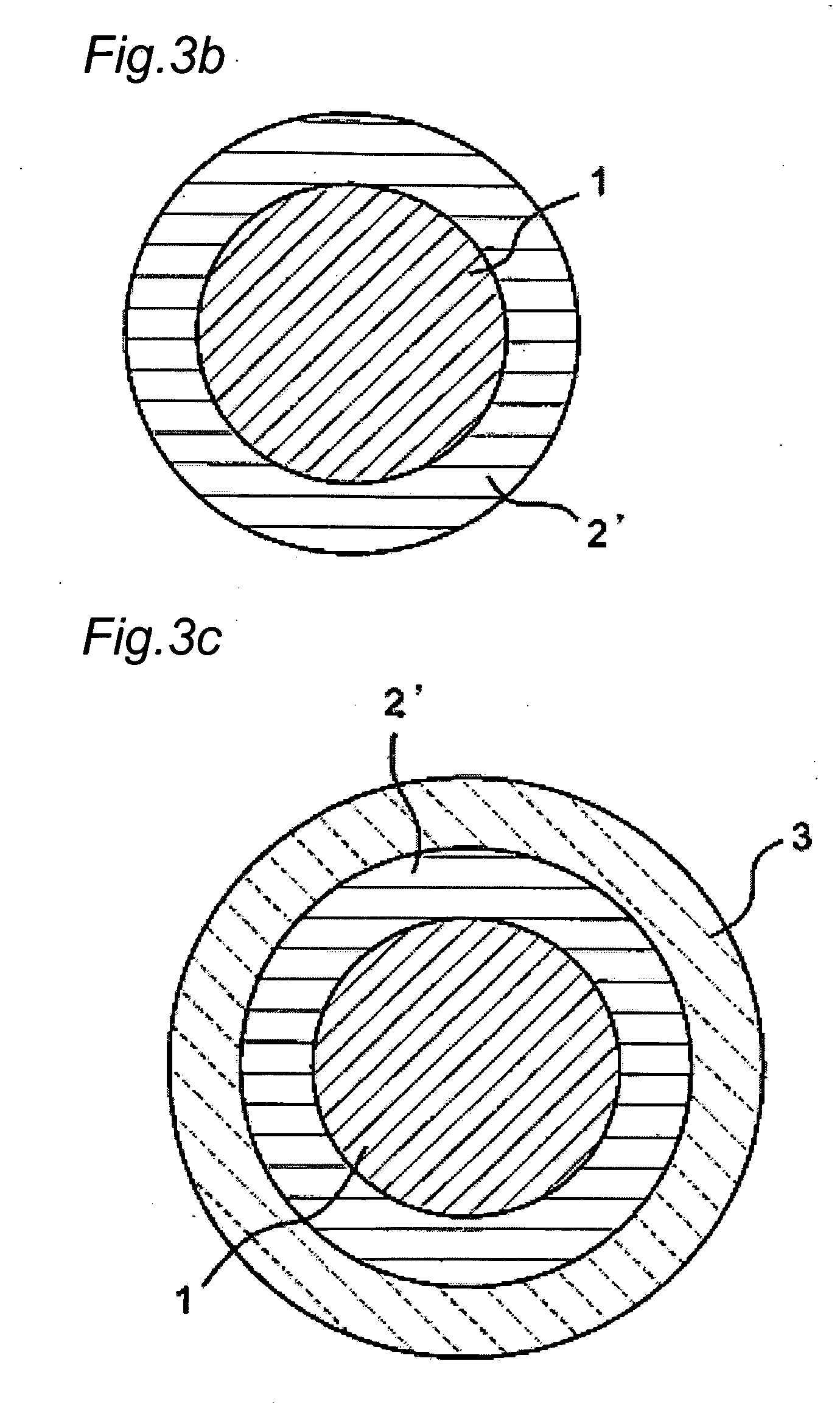
[0052]Preferred embodiment of the method for producing a catalyst according to the present invention will be described below with reference to FIG. 3a.
1) Preparation of Core Portion 1
[0053]A core portion 1 containing a catalyst is prepared (FIG. 3a). A nano-scale...
embodiment 2
[0079]Subsequently, the catalyst according to Embodiment 2 of the present invention will be described below. Embodiment 2 is different from Embodiment 1 in that photocatalyst particles are used as catalyst particles.
[0080]The catalyst according to the present invention includes a core portion 1 containing a photocatalyst excited by light irradiation and a porous layer 3 formed so as to cover over the core portion 1, and a hollow layer 2 is formed between the core portion 1 and the porous layer 3.
[0081]Since the porous layer 3 has a porous structure, when substances such as toxic substances and odors penetrate into the porous layer 3 and these substances are irradiated with ultraviolet light in a state of contacting with the core portion 1 containing the photocatalysts, the photocatalysts are photoexcited to form electrons and holes and thus pollutants and odors in the vicinity of the surface of the photocatalyst are decomposed by a radical generated by charges.
[0082]The photocatalys...
example 1
[0091]The catalyst according to Example 1 will be described in detail below. In Example 1, strontium titanate (SrTiO3) was used as photocatalyst particles contained in the core portion 1.
[0092]First, platinum was supported on strontium titanate (SrTiO3) manufactured by FUJI TITANIUM INDUSTRY CO., LTD. using a photoelectrodeposition method to obtain Pt-supported strontium titanate (hereinafter referred to as Pt—SrTiO3, “Pt—” as used herein means to support Pt). Pt—SrTiO3 suspended in an aqueous glucose solution was subjected to a hydrothermal treatment at 180° C. to obtain carbon-coated Pt—SrTiO3 (hereinafter referred to as c / Pt—SrTiO3, “c / ” as used herein means to coat with carbon). The carbon-coated Pt—SrTiO3 thus obtained was reacted with tetraethoxysilane (TEOS) thereby coating the surface with silica (referred to as si / c / Pt—SrTiO3, “si / c / ” as used herein means that a silica layer is formed on a carbon layer after forming the carbon layer), and then carbon was removed by subjecti...
PUM
| Property | Measurement | Unit |
|---|---|---|
| Catalytic activity | aaaaa | aaaaa |
Abstract
Description
Claims
Application Information
 - R&D Engineer
- R&D Manager
- IP Professional
- Industry Leading Data Capabilities
- Powerful AI technology
- Patent DNA Extraction
Browse by: Latest US Patents, China's latest patents, Technical Efficacy Thesaurus, Application Domain, Technology Topic, Popular Technical Reports.
© 2024 PatSnap. All rights reserved.Legal|Privacy policy|Modern Slavery Act Transparency Statement|Sitemap|About US| Contact US: help@patsnap.com