Method for producing a rare earth-based magnet
- Summary
- Abstract
- Description
- Claims
- Application Information
AI Technical Summary
Benefits of technology
Problems solved by technology
Method used
Image

Examples
Embodiment Construction
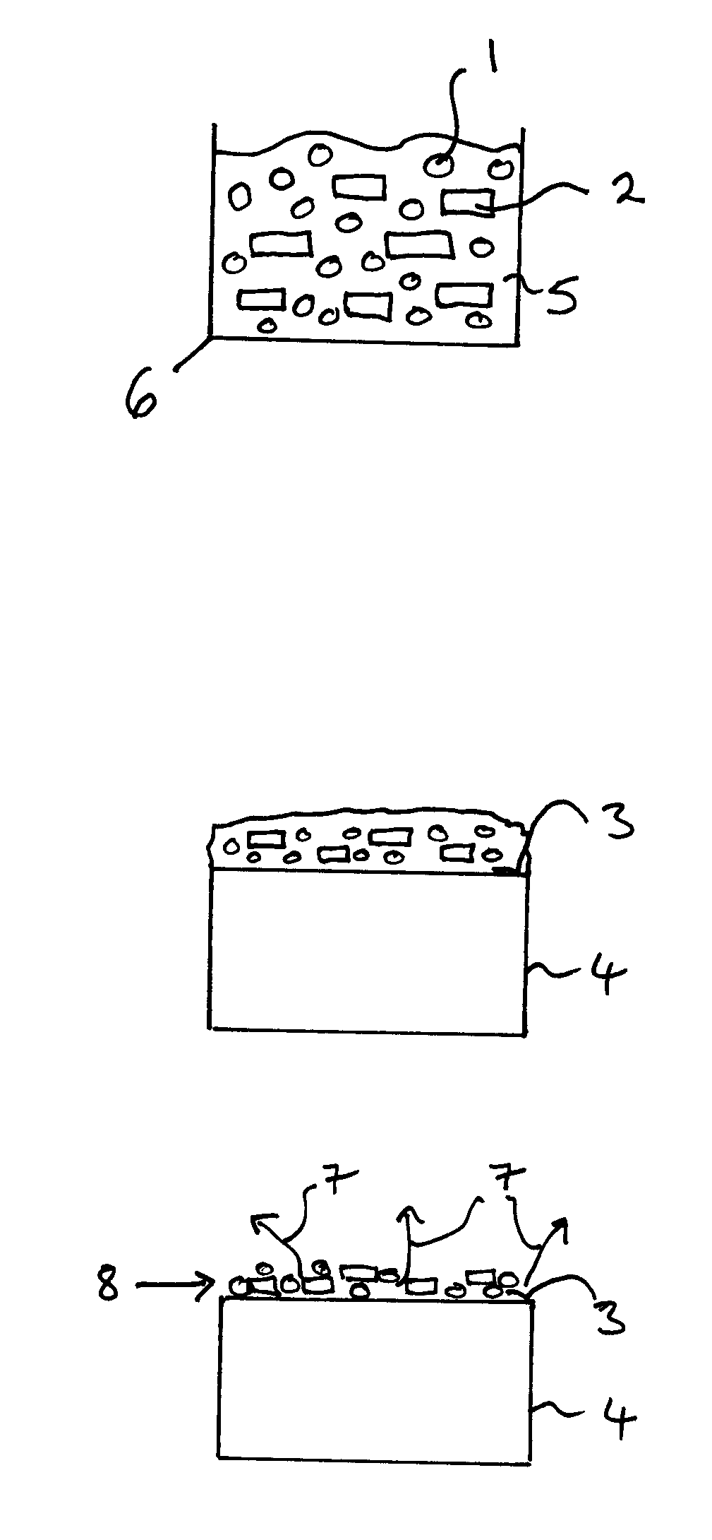
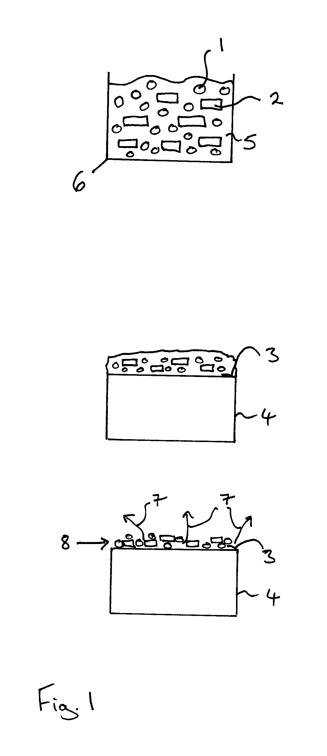
[0079]FIG. 1 illustrates a method of applying first particles 1 comprising a rare earth element and second particles 2 comprising a separating material to a first surface 3 of a rare earth-based magnet 4, in particular a precursor sintered R2Fe14B-type magnet.
[0080]In this particular embodiment, R is a mixture of neodymium and dysprosium. The further material of second particles 2 is neodymium oxide and the first particles 1 comprising a rare earth element R′ are dysprosium hydride.
[0081]For illustrative purposes, the first particles 1 comprising the rare earth element R′ are illustrated as having a generally circular form and the second particles 2 of the further material are illustrated as having a rectangular form. However, these two forms are merely used to distinguish the two types of particles from one another in the drawings and are not intended to describe the shape of the particles. The first particles 1 of the rare earth element R′ and the second particles 2 of the further...
PUM
 Abstract
Description
Claims
Application Information