System and method for measurement of an impedance using a catheter such as an ablation catheter

a technology of impedance measurement and ablation catheter, which is applied in the field of system and method of measuring an impedance using an ablation catheter, can solve the problems of inaccurate reading that is not completely indicative of the actual tissue condition, the measurement of two-terminal impedance is subject to variation, and the ablation may generate excessive heat, so as to achieve the effect of maximizing the predetermined distance and improving the accuracy of determining

Active Publication Date: 2009-07-02
ST JUDE MEDICAL ATRIAL FIBRILLATION DIV
View PDF42 Cites 101 Cited by
  • Summary
  • Abstract
  • Description
  • Claims
  • Application Information

AI Technical Summary

Benefits of technology

[0009]In one embodiment, a system is provided that is suitable for use with an apparatus that has a four-wire interface comprising a pair of source connectors (positive and negative) and a pair of sense connectors (positive and negative). While this apparatus may be a stand-alone unit, the invention allows for combination with other equipment, such as a radio frequency (RF) ablation generator. The system includes a catheter having a tip electrode, a source return and a sense return (e.g., the returns may be conductive patches suitable for affixation to the body). In practical RF ablation embodiments, an RF indifferent (dispersive) return (electrode) would also be provided to cooperate with the ablation tip electrode. The catheter includes an elongated shaft having a proximal end and a distal end. The tip electrode is disposed at the distal end. A source lead is electrically connected to the tip electrode and extends through the shaft of the catheter to its proximal end, where it is destined for connection to the positive source connector. The source and sense returns are configured for connection to respective negative source and sense connectors at the apparatus. The apparatus is configured to produce an excitation signal across the source connectors. The excitation signal is an alternating current (AC) signal whose frequency is preferably selected, in RF ablation embodiments, so as to not interfere with the RF ablation frequency. The excitation signal, when applied by way of the tip electrode, will result in a response signal, which is measured across the sense connectors and used in determining the complex impedance of the tissue proximate the tip electrode. For example, when the excitation signal is a constant current AC signal, an AC voltage signal is produced in response over the complex load (i.e., tissue), which is then measured across the sense connectors.
[0010]In a further embodiment, the source and sense returns are combined in a single patch with separate sections of conductive material. In a still further preferred embodiment, however, the source and sense returns are in separate patches that are spaced apart by a predetermined distance. Still more preferably, these two patches are located on opposite sides of a patient so as to maximize the predetermined distance. In either case (single patch / two patches), the tip electrode defines a first terminal while the separate source / sense returns defines the second and third terminals, respectively. As described in greater detail herein, this four-wire, three-terminal measurement arrangement provides for improved performance in determining the complex impedance in the tissue volume proximate the tip electrode.
[0011]In a still further embodiment, the system includes a cable (i.e., supply cable) having a first end configured for connection to the apparatus (e.g., RF ablation generator) and a second end configured for connection to the catheter. The cable has a source conductor and a separate sense conductor. The source and sense conductors are terminated separately at the first end for respective, separate connections to the positive source and sense connectors. The source and sense conductors are electrically joined (with each other) at the second end for a single connection to the source lead of the catheter, which runs to the tip electrode. In this embodiment, a single lead through the catheter is used for impedance measurements.
[0012]In addition, a two-lead catheter according to the invention is also presented. In a still further embodiment, one of the source or sense returns is combined with the RF indifferent return mentioned above (i.e., that is to be used for the RF ablation) and a catheter ring electrode is used for the other one of the source / sense returns. Still other variations are presented.
[0013]The foregoing and other aspects, features, details, utilities, and advantages of the present invention will be apparent from reading the following description and claims, and from reviewing the accompanying drawings.

Problems solved by technology

RF ablation may generate excessive heat if not controlled.
However, one shortcoming in the art is that such two-terminal measurements are subject to variation in the measurement of impedance due to factors unrelated to the condition of the tissue (i.e., non-physiologic changes).
For example, coiling of an ablation cable that connects the ablation generator to the catheter can alter the impedance measurement, providing an inaccurate reading that is not completely indicative of the actual tissue condition.
However, these other measurement techniques do not address the problems described above.

Method used


Image

  • System and method for measurement of an impedance using a catheter such as an ablation catheter
  • System and method for measurement of an impedance using a catheter such as an ablation catheter
  • System and method for measurement of an impedance using a catheter such as an ablation catheter

Examples


first embodiment

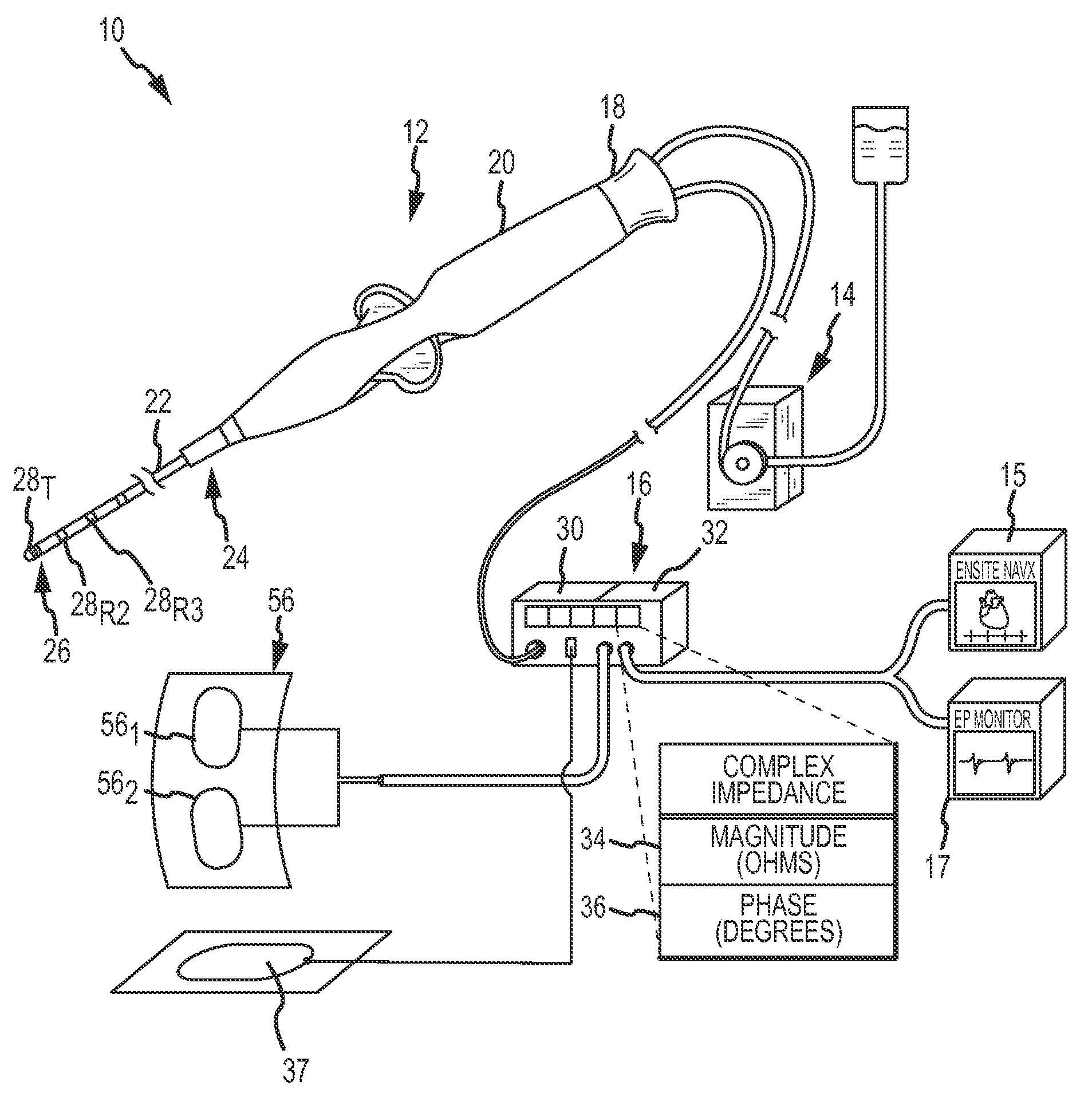
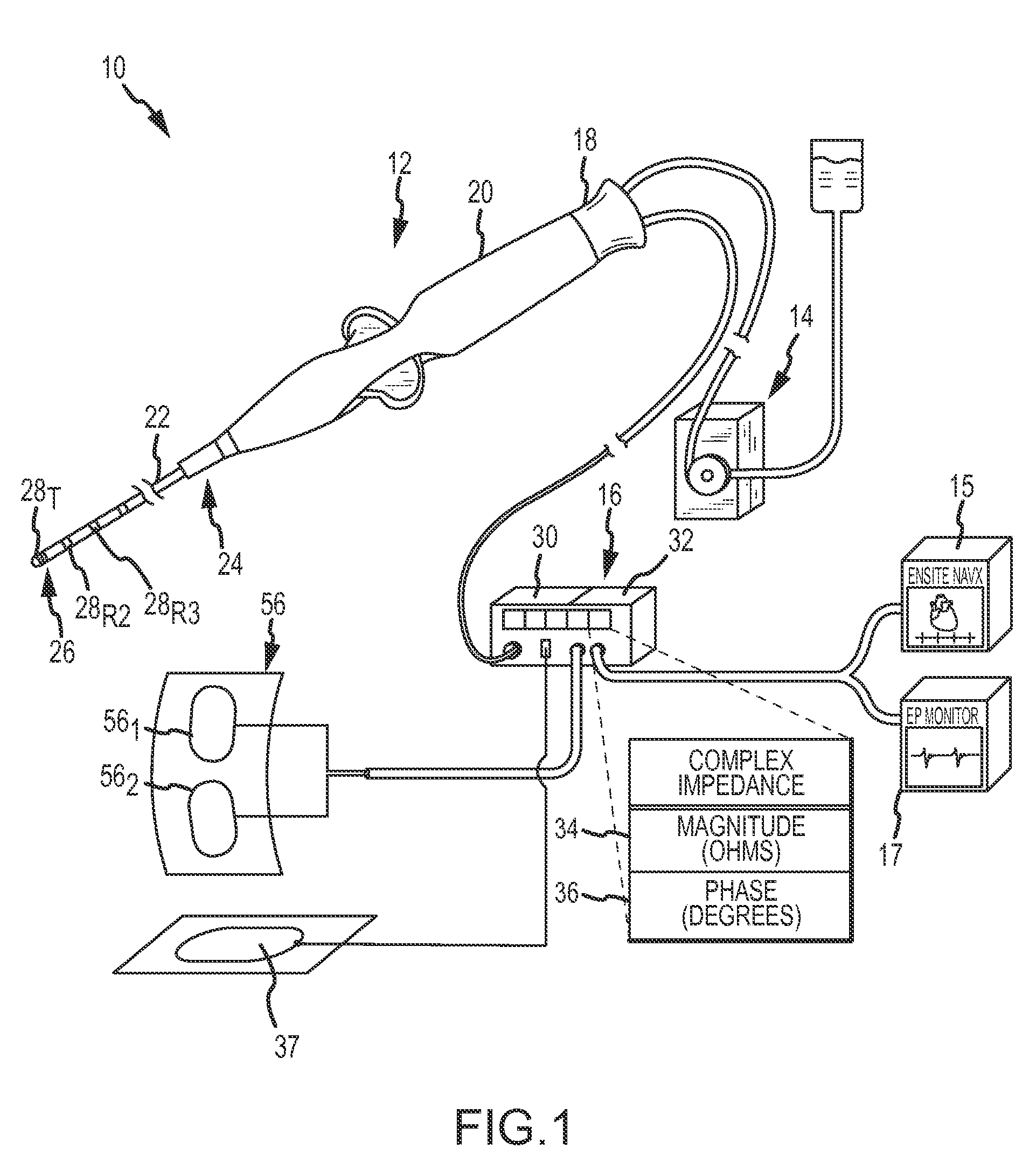
[0043]FIG. 3A is a diagrammatic view of a system according to the present invention. FIG. 3A shows the catheter 12 with the ablation (tip) electrode 28T at the distal end. The tip electrode 28T may comprise conventional configurations as to size, shape and materials. In one embodiment, the tip electrode 28T may be for example only a 2.5 mm, a 4 mm or an 8 mm length ablation electrode.

[0044]The catheter 12 include a source lead 46 (SOURCE (+)) electrically coupled to the tip electrode 28T and extending through the shaft 22 to the proximal end where it is terminated. The source lead 46 is configured in this embodiment to carry the RF ablation energy and in this regard may comprise conventional materials such as insulated copper wire or the like. In one embodiment, the source lead 46 may be 32 AWG or 34 AWG copper wire.

[0045]The catheter 12 also includes a sense lead 48 (SENSE (+)) electrically coupled to the tip electrode 28T and extending through the shaft 22 to the proximal end wher...

second embodiment

[0049]FIG. 3B is a diagrammatic view of the invention, which is the same as shown in FIG. 3A, except that is employs a different reference electrode wiring configuration, designated 54′. The wiring configuration 54′ deploys the source and sense returns as physically separate patches 56A and 56B so as to allow independent placement of each to achieve a predetermined distance 57 between them. In a preferred embodiment, the distance 57 should be a maximum obtainable, which is typically on opposite sides of a patient (e.g., Left-Right or Front-Back). The increase in the separation distance reduces the amount of overlap between the source and sense paths and accordingly focuses the impedance measurement to just that tissue volume closest to the tip electrode, which is generally what is desired.

third embodiment

[0050]FIG. 3C is a diagrammatic view of the present invention, which is the same as the embodiment of FIG. 3A, except for a variation in the connecting cable(s) and the catheter. Particularly, an alternate catheter embodiment, catheter 12′, uses a single lead, namely, a combined source / sense lead 46 / 48 rather than two separate leads. The combined lead is electrically connected to the tip electrode 28T and extends through the shaft 22 to the proximal end where it is terminated in the connector interface 18. The combined lead 46 / 48 may be of the same construction as the source lead 46 in FIG. 3A. Of the cables 50 and 52, it is contemplated that the one that is to connect to the catheter 12′ will be modified. Thus, if no extension cable is used, then the generator cable 52 will be modified. If the extension cable 50 is used, then it will be modified, and the generator cable will be unmodified. More specifically, the modification involves the end connecting to the catheter 12′, where th...


PUM


Abstract

A catheter and patch electrode system is provided for use with an apparatus, such as an ablation generator, having a 4-wire interface for improved impedance measurement. The 4-wire interface includes a pair of source connectors across which an excitation signal is produced and a pair of sense connector wires across which the impedance is measured. The RF ablation generator may also produce an ablation signal across a source wire and an indifferent return patch electrode. The system further includes a cable that connects the generator to a catheter. The catheter includes a shaft having a proximal end and a distal end, with an ablation tip electrode disposed at the distal end. A source lead is electrically coupled to the tip electrode and extends through the shaft to the proximal end where it is terminated. An optional sense lead is also electrically coupled to the tip electrode and extends through the shaft to the proximal end. The system further includes a source return (e.g., skin patch) and a sense return (e.g., skin patch), either or none of which may be combined with the indifferent return, and if used may be placed on opposite sides of the patient for improved performance. The impedance sensor circuit produces an excitation signal across the source connectors, which is then carried to the catheter by the cable, then to the tip electrode, travels through the complex load (tissue volume), and returns to the generator via a patch electrode. The impedance is measured by observing the voltage drop across the sense connectors caused by the excitation signal.

Description

BACKGROUND OF THE INVENTION[0001]a. Field of the Invention[0002]The instant invention relates to a system and method for measuring an impedance using an ablation catheter.[0003]b. Background Art[0004]Electrophysiology (EP) catheters have been used for an ever-growing number of procedures. For example, catheters have been used for diagnostic, therapeutic, mapping and ablative procedures, to name just a few examples. Typically, a catheter is manipulated through the patient's vasculature and to the intended site, for example, a site within the patient's heart, and carries one or more electrodes, which may be used for mapping, ablation, diagnosis, or other treatments.[0005]There are a number of methods used for ablation of desired areas, including, for example, radio frequency (RF) ablation. RF ablation is accomplished by transmission of radio frequency energy to a desired target area through an electrode assembly to ablate tissue at the target site. RF ablation may generate excessive h...

Claims


Application Information

Patent Timeline
Patent Type & Authority Applications(United States)
IPC IPC(8): A61B18/16
CPCA61B18/1206A61B2018/00875A61B2018/00577A61B18/1492A61B2018/165
Inventor MILLER, STEPHAN P.KASTNER, GLEN H.DENO, D. CURTIS
Owner ST JUDE MEDICAL ATRIAL FIBRILLATION DIV
Why Eureka
Try Eureka