System and Method of Leakage Control in an Asynchronous System

a leakage control and asynchronous technology, applied in the direction of instruments, power consumption reduction, liquid/fluent solid measurement, etc., can solve the problems of limited application of components and the consumption of electrical components, and achieve the effects of reducing power consumption, reducing leakage current, and high degree of granularity

Active Publication Date: 2009-07-02
QUALCOMM INC
View PDF12 Cites 10 Cited by
  • Summary
  • Abstract
  • Description
  • Claims
  • Application Information

AI Technical Summary

Benefits of technology

[0009]A particular advantage provided by the disclosed embodiments is reduced power consumption due to lower leakage current by powering off unused circuit elements at a high degree of granularity. Individual stages of an asynchronous pipeline may be selectively decoupled from a power supply without an offsetting increase in dynamic clock power consumption.

Problems solved by technology

However, electronic components consume power even when not actively in use, such as leakage currents due to properties of transistors and other components.
Although some electronic components have been proposed that include a switch to reduce power by decoupling the component from a positive voltage source (a head switch) or a ground (a foot switch) using state logic coupled to a system clock, such components have limited application due to the dynamic clock power consumption required for each component.

Method used


Image

  • System and Method of Leakage Control in an Asynchronous System
  • System and Method of Leakage Control in an Asynchronous System
  • System and Method of Leakage Control in an Asynchronous System

Examples


Embodiment Construction

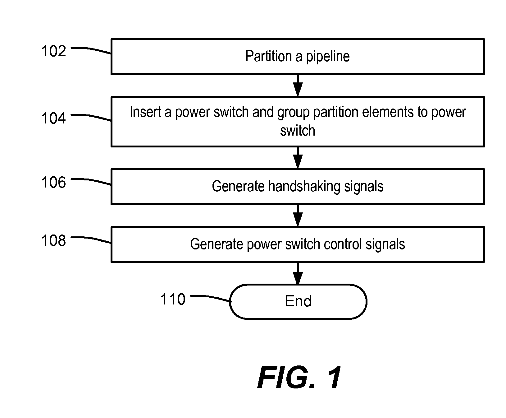
[0017]Referring to FIG. 1, a particular illustrative embodiment of a method of leakage control in an asynchronous system is depicted. At 102, a pipeline is partitioned. The pipeline may be a processing pipeline of a digital system. In an illustrative embodiment, the pipeline includes at least two logical stages that may be executed serially. For example, a state of a predecessor stage of the pipeline may affect an outcome of a successor stage of the pipeline.

[0018]Advancing to 104, a power switch is inserted and partition elements are grouped to the power switch. Partition elements may include circuit devices and logic coupled to the power switch, such as circuit devices coupled to a system ground via a foot switch or coupled to a supply voltage via a head switch.

[0019]Moving to 106, handshaking signals are generated. In a particular embodiment, handshaking signals are generated by and exchanged between two or more control logic circuits along the pipeline. For example, each stage o...


PUM


Abstract

Systems and methods of leakage control in an asynchronous pipeline are disclosed. In an embodiment, a signal is received from a preceding stage at an operative stage of an asynchronous circuit device, and a switch associated with the operative stage is activated in response to the control signal being sent to the operative stage to enable power to the operative stage.

Description

I. FIELD[0001]The present disclosure is generally related to a system and method of leakage control in an asynchronous system.II. DESCRIPTION OF RELATED ART[0002]Advances in technology have resulted in smaller and more powerful personal computing devices. For example, there currently exist a variety of portable personal computing devices, including wireless computing devices, such as portable wireless telephones, personal digital assistants (PDAs), and paging devices that are small, lightweight, and easily carried by users. More specifically, portable wireless telephones, such as cellular telephones and IP telephones, can communicate voice and data packets over wireless networks. Further, many such wireless telephones include other types of devices that are incorporated therein. For example, a wireless telephone can also include a digital still camera, a digital video camera, a digital recorder, and an audio file player. Also, such wireless telephones can process executable instruct...

Claims


Application Information

Patent Timeline
Patent Type & Authority Applications(United States)
IPC IPC(8): G06F1/26
CPCH03K19/0016G06F9/3871
Inventor KONG, XIAOHUACHUA-EOAN, LEW G.YOON, SEI SEUNGZHU, ZHI
Owner QUALCOMM INC
Why Eureka
Try Eureka