System and method for soil strength measurement

a soil strength and measurement system technology, applied in the field of measurement systems and methods, can solve the problems of inability to adapt to automation, subjective and inaccurate data of cone penetrometers, and large manual operations

Inactive Publication Date: 2009-07-09
INTELLISENSE SYST INC
View PDF4 Cites 19 Cited by
  • Summary
  • Abstract
  • Description
  • Claims
  • Application Information

AI Technical Summary

Benefits of technology

[0012]Commercially available sensors can be used to measure the distance from the sensors (preferably mounted to a fixed mounting point on the vehicle) to the surface of the ground. For example, optical measurement of distances using laser triangulation devices provides suitable results to an accuracy acceptable for soil strength calculations. The system can be configured such that data can be read from multiple sensors and further configured to allow differential measurement from a moving platform. In one embodiment, this can be used to avoid processing otherwise required to accommodate platform bouncing.
[0013]The use of optical, ultra wideband, or other like measurement technologies can be used to provide a non-invasive, automatic method to measure the deformation of the upper soil layer in reaction to the load provided by a wheel of a moving vehicle. As noted, in one embodiment, a front wheel of the vehicle is used as that object can be measured as compared to soil that has been untouched by the vehicle. In one embodiment, the sensors can be configured to take measurements from a regular wheel of a vehicle such that no additional wheels are required to perform the measurements.

Problems solved by technology

Field data can be acquired with a hand-held cone penetrometer, and even in the best of circumstances, cone penetrometer data are subjective and inaccurate.
All methods listed above provide measurement of soil strength only in discreet points, require extensive manual operations and are not well suited to automation.

Method used


Image

  • System and method for soil strength measurement
  • System and method for soil strength measurement
  • System and method for soil strength measurement

Examples


Embodiment Construction

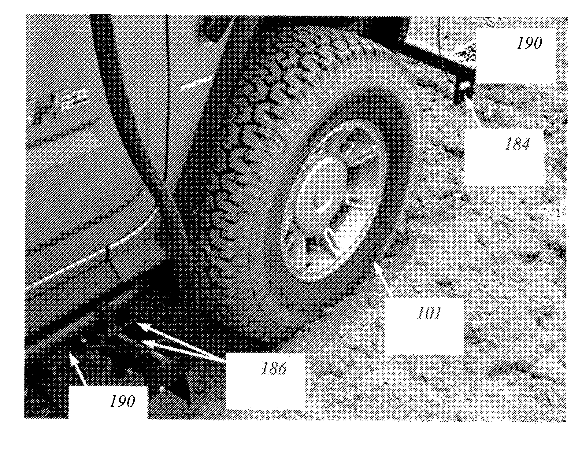
[0010]According to various embodiments of the invention optical, ultra-wideband or other distance measuring devices can be mounted to a vehicle and used to determine the distance between the sensors and the soil surface being measured. Preferably, multiple sensors can be used to measure distances from the sensors to the ground in areas where a wheel of the vehicle has traveled as well as areas where the wheel has not traveled. The measurements can be compared to determine the depth of a track made by the tire or wheel of a vehicle as the vehicle traveled along on the soil. The track depth can be used to determine parameters such as, for example, a cone index or a rating cone index.

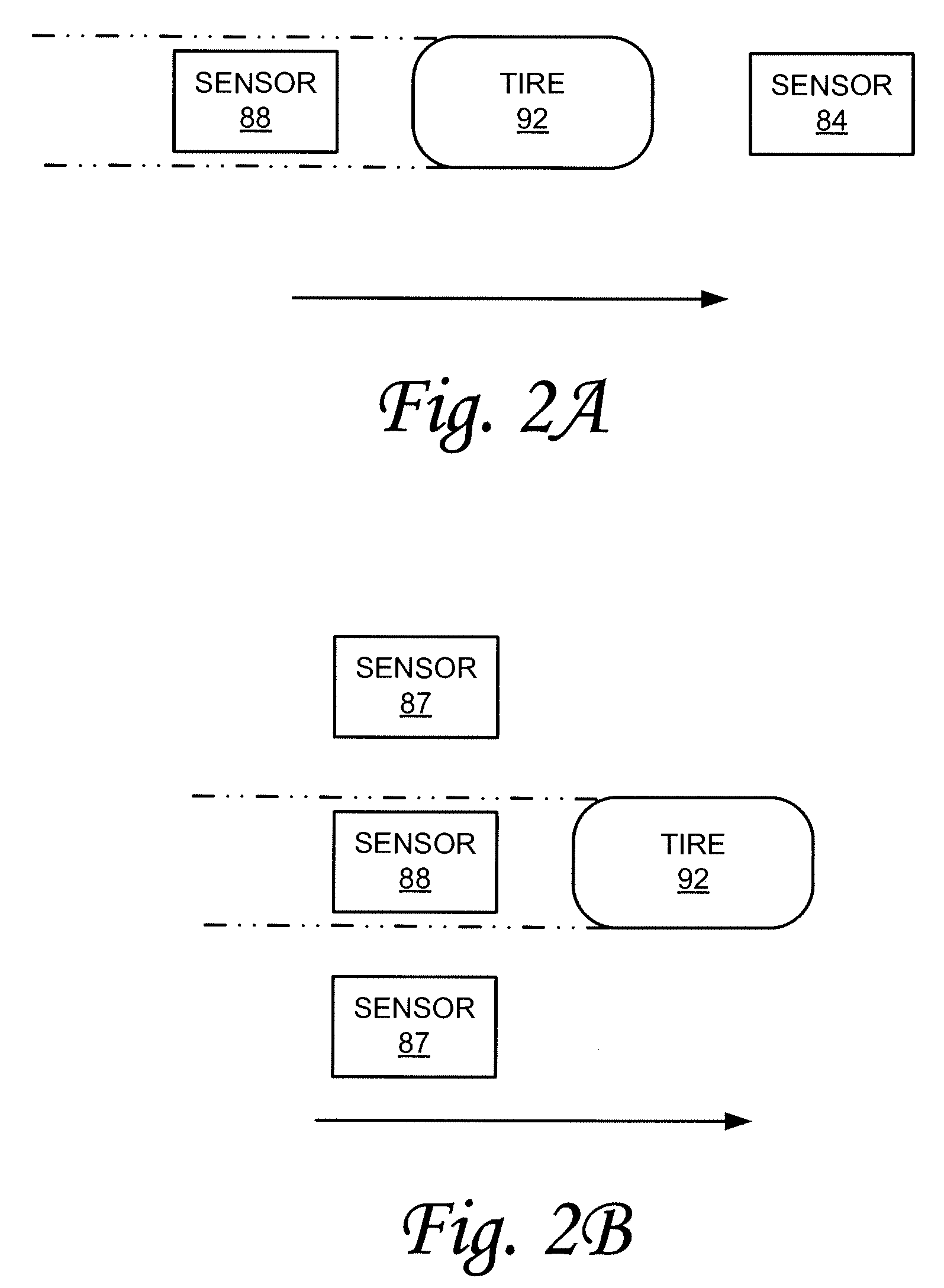
[0011]Various sensor configurations can be utilized to measure and determined track depth, which is used to calculate soil strength. For example, sensors can be located in front of and behind a given wheel of the vehicle to measure the distance from the sensor to the surface of the ground both in front of ...


PUM


Abstract

A system and method for characterizing soil shear strength from a vehicle, comprises a plurality of sensors mounted on a vehicle and configured to measure distances from the sensors to the soil surface. The sensors comprise a first sensor disposed on the vehicle and configured to measure a first distance between the first sensor and the soil and a second sensor disposed on the vehicle and configure to measure a second distance between a the sensor and a track made in the soil by the vehicle, wherein the first sensor measures the distance at a location before the vehicle wheel travels over that location and the second sensor measures the distance to the bottom of the track made by the wheel. A processing module is communicatively coupled to the sensors and is configured to calculate track depth as a function of the first and second distance measurements; and to derive soil shear strength as a function of the calculated track depth and the vehicle parameters.

Description

TECHNICAL FIELD[0001]The present invention relates to measurement systems and methods, and more particularly, some embodiments relate to soil density, soil shear resistance or soil penetration resistance measurement.DESCRIPTION OF THE RELATED ART[0002]Soil strength is a measure of the capacity of soil to resist deformation and can be discussed in terms of the amount of energy required to break apart aggregates or move implements through the soil or a measure of the amount of weight a given area will satisfactorily support. Field determination of soil strength is a common geotechnical procedure that is routinely carried out for a variety of different purposes. For example, soil strength determinations are useful to determine the loading characteristics of the soil for evaluating sites for construction of buildings and roads, design footings, airfields and the like; evaluation of terrain trafficability for passing personal, commercial and military vehicles; and estimation of impact in...

Claims


Application Information

Patent Timeline
Patent Type & Authority Applications(United States)
IPC IPC(8): G01B5/18
CPCE02D1/022
Inventor SANDOMIRSKY, SERGEYJANNSON, TOMASZSHNITSER, PAULSAVANT, GAJENDRA
Owner INTELLISENSE SYST INC
Why Eureka
Try Eureka