
Process to provide a particulate solid material to a pressurised reactor

Active Publication Date: 2009-07-16
AIR PROD & CHEM INC
View PDF23 Cites 30 Cited by
  • Summary
  • Abstract
  • Description
  • Claims
  • Application Information

AI Technical Summary

Benefits of technology

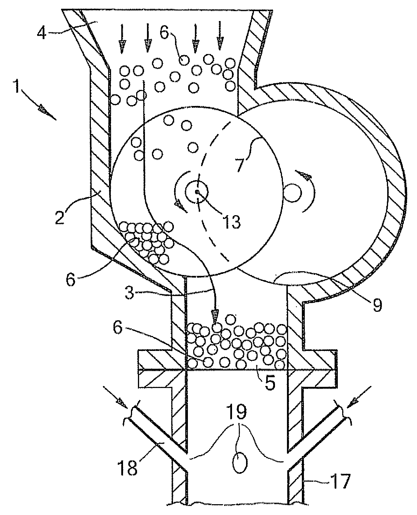
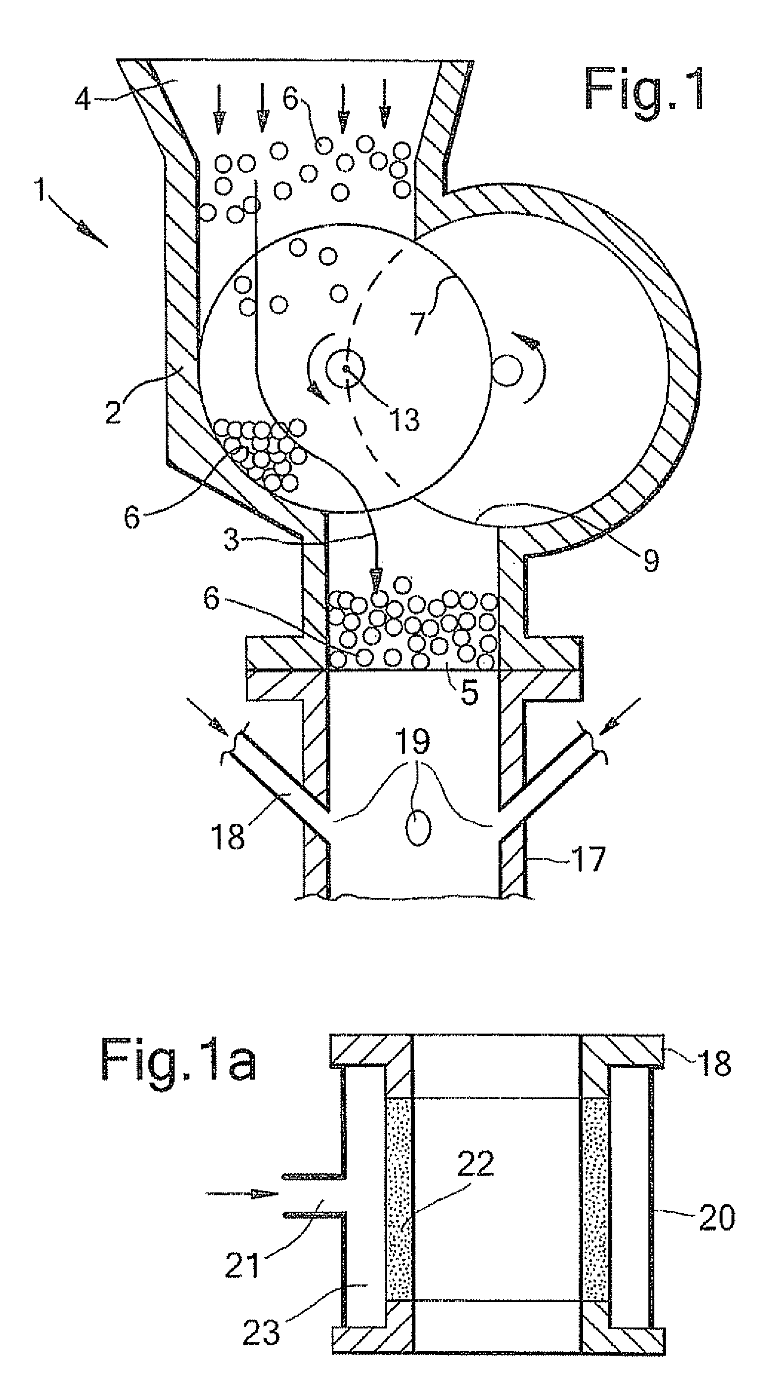
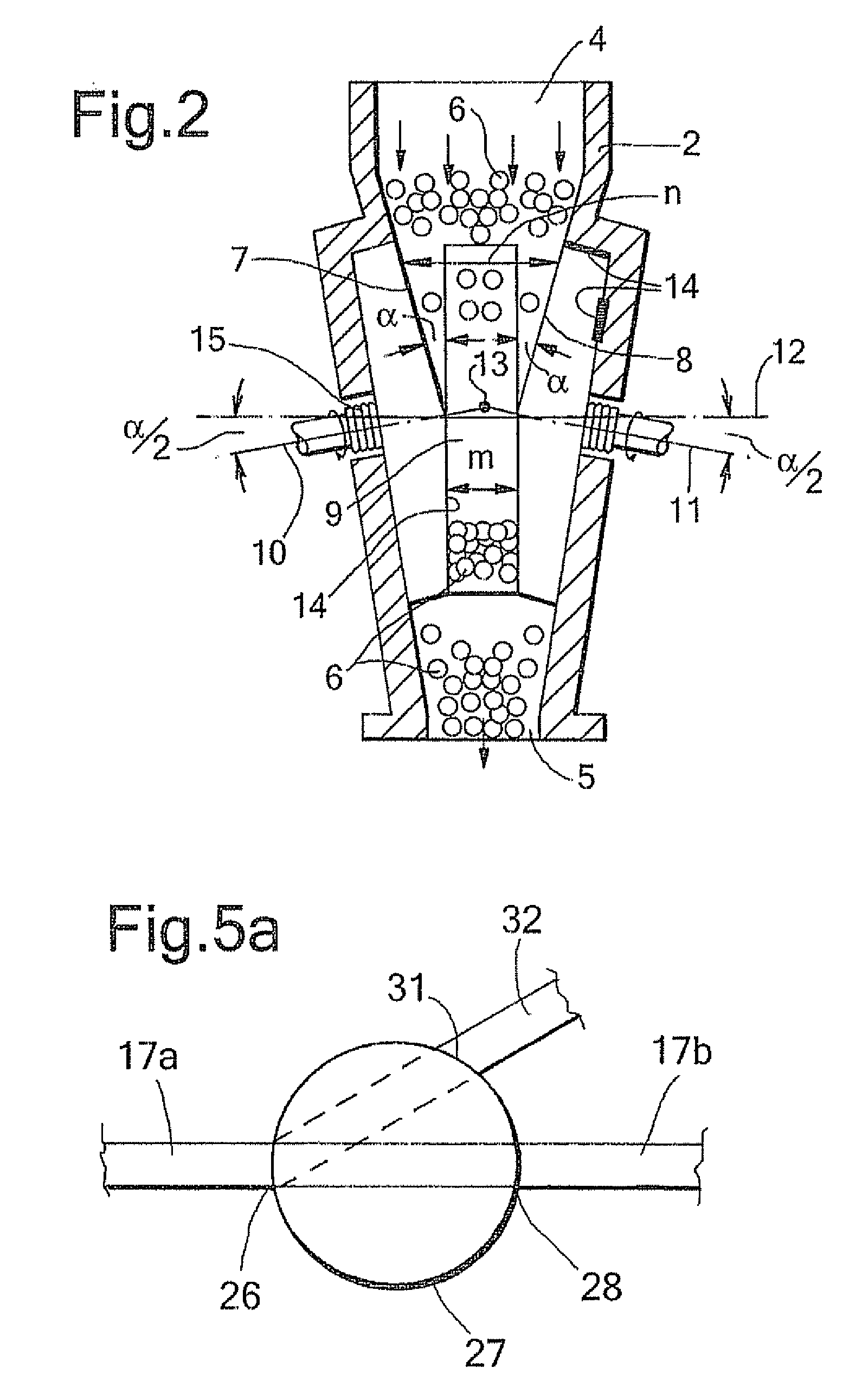
[0010]Applicants have found that the process according to the invention makes it possible to directly feed the particulate solid material to the pressurised reactor. The use of the gaseous stream is beneficial in that it breaks open the compacted cake as it is discharged from the solids pump. The gaseous stream subsequently carries the solids as a homogeneous mixture of solids and gas through the transport conduit to the pressurised reactor as a stable flow. Another advantage is that the solids flow to the reactor can be directly influenced by varying the rotational speed of the drive disks.

Problems solved by technology

A disadvantage of using such a lock hopper design is the cycling of multiple batch tanks, the disruptions that occur when one such tank is taken off line and another is started and the venting of significant quantities of pressurising gas.
It is described that many types of equipment have been developed but thus far none have been very successful because they are vulnerable for erosion and fouling.
A disadvantage of the process of U.S. Pat. No. 5,657,704 is the presence of a high-pressure feeder tank between the solids pump and the pressurised reactor.
Because of this intermediate feeder tank it is not possible to directly control the flow of solids to the pressurised reactor by controlling the rotational speed of the solids pump itself.

Method used


Image

  • Process to provide a particulate solid material to a pressurised reactor
  • Process to provide a particulate solid material to a pressurised reactor
  • Process to provide a particulate solid material to a pressurised reactor

Examples


Embodiment Construction

[0019]With the term lower pressure zone is meant the zone at which the carbonaceous solid material is present before being fed to step (a) of the process of the present invention. Suitably the pressure of this zone is ambient or about ambient pressure, i.e. 1 bara. With the term higher-pressure zone is meant the zone directly downstream the bulk materials pump. The pressure range of the higher pressure zone is suitably equal to the preferred pressure range as specified for the gasification reactor.

[0020]The solid material is preferably a carbonaceous or a particulate solid material and more preferably a particulate solid carbonaceous material. Herein the solid material may sometimes also be referred to as particulate material or carbonaceous material.

[0021]The solid material is preferably coal, petroleum coke or a solid biomass. Examples of suitable coal types are anthracite, brown coal, bitumous coal, sub-bitumous coal and lignite.

[0022]Solid biomass particulate matter is preferabl...


PUM


Abstract

The invention is directed to a process to provide a particulate solid carbonaceous material to a pressurised gasification reactor comprising following steps, (a) transporting the solid material from a first lower pressure zone to a higher pressure zone using a bulk materials pump comprising a housing having a flow path for the solid material between an inlet fluidly connected to the first lower pressure zone and an outlet fluidly connected to the higher pressure zone, wherein said flow path in said housing is further defined by a space between two rotatable drive disks spaced from each other and wherein a materials scraper is present between said drive disks at the outlet to route a cake of solid material that is being transported between said drive disks to a transport conduit, which transport conduit fluidly connects the outlet of said housing and a burner as present in the gasification reactor, and (b) injecting a gaseous stream into the cake of solid material where the cake of solid material is discharged from the housing and enters the transport conduit, and (c) transporting the solid material and the gaseous stream in a transport conduit to the burner.

Description

[0001]This patent application claims the benefit of European patent application No. 08100545.6, filed Jan. 16, 2008 and U.S. Provisional Application 61 / 024457, filed Jan. 29, 2008, both of which are incorporated herein by reference.FIELD OF THE INVENTION[0002]The invention is directed to a process to provide a particulate solid material to a pressurised reactor.BACKGROUND OF THE INVENTION[0003]U.S. Pat. No. 3,402,684 is directed to a process to provide bark from an atmospheric pressure portion to a subatmospheric pressure portion.[0004]WO-A-99 / 66008 describes a fixed bed gasification reactor for municipal waste.[0005]In a coal gasification process pulverised coal is fed to a pressurised gasification reactor either as a dry solid or as a slurry. A commercial process to pressurize dry pulverised coal comprises the use of a lock hopper as described in Chapter 6.2 in Gasification, by Christopher Higman and Maarten van der Burgt, 2003, Elsevier Science, Burlington Mass., Pages 173-177. A...

Claims


Application Information

Patent Timeline
IPC IPC(8): C10J3/68C10J3/00C10J1/207
CPCB01J8/003B01J8/0045B01J2208/00752C10J3/482Y02E50/32C10J2200/156F04D5/001F04D23/003C10J2200/15Y02E50/30
Inventor VAN DER PLOEG, GOVERT GERARDUS PIETER
Owner AIR PROD & CHEM INC
Learn More