Sputter coating device

a coating device and sputter technology, applied in coatings, vacuum evaporation coatings, electrolysis components, etc., can solve the problems of high price of cylindrical targets b>6/b> for rotatable cathodes, and inability to meet the requirements of all materials,

Inactive Publication Date: 2009-07-16
APPLIED MATERIALS INC
View PDF12 Cites 15 Cited by
  • Summary
  • Abstract
  • Description
  • Claims
  • Application Information

AI Technical Summary

Benefits of technology

[0009]It is an object of the present invention to provide a sputter coating device for the use of planar targets, wherein the sputter coating device has a coating quality and efficiency comparable with the coating quality provided by rotatable magnetrons.

Problems solved by technology

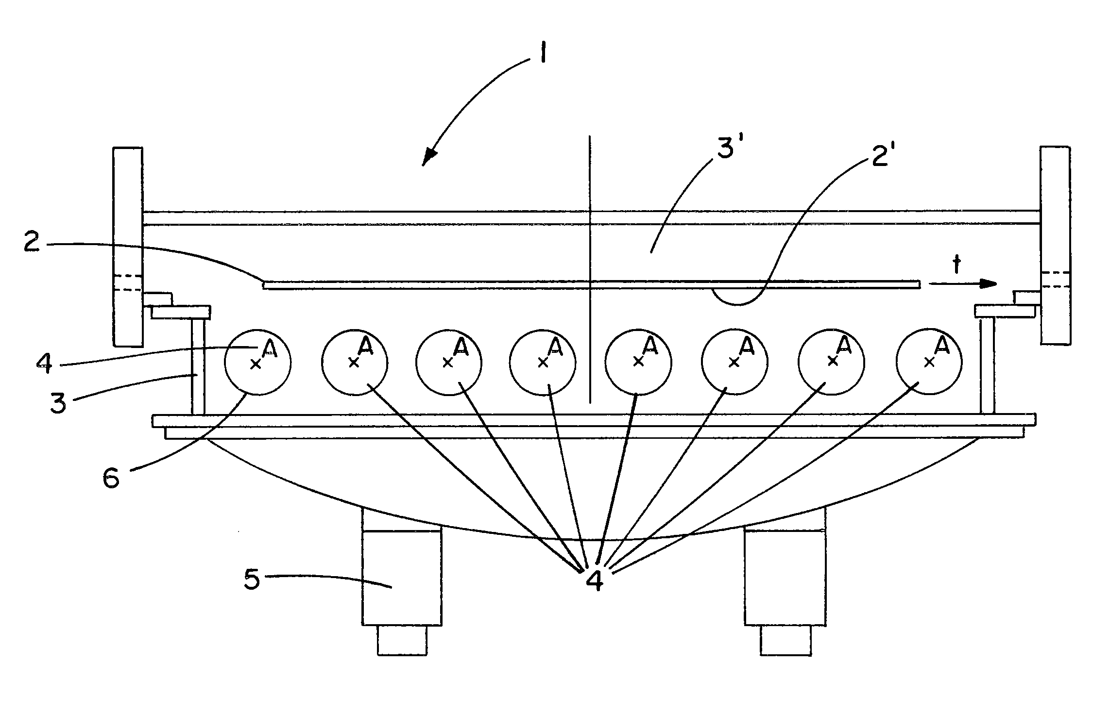
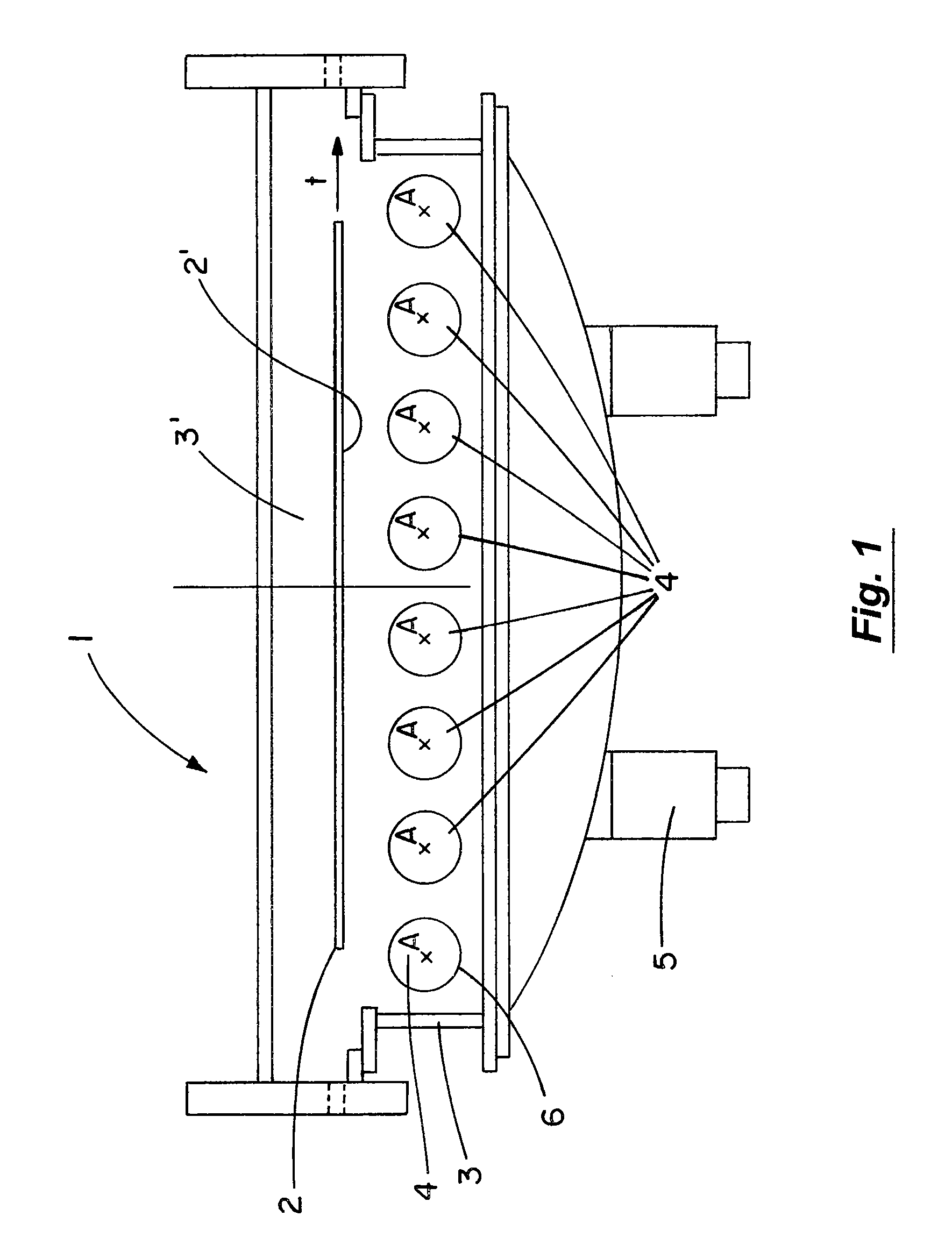
However, cylindrical targets 6 are not available for all materials.
Furthermore, cylindrical targets 6 for rotatable cathodes 4 are quite expensive.

Method used


Image

  • Sputter coating device
  • Sputter coating device
  • Sputter coating device

Examples


Embodiment Construction

[0040]FIG. 3 depicts a target unit 9 according to the present invention. The target unit 9 is a cathode unit or magnetron unit and comprises a target 6 and a housing 10. The housing 10 is attached to the target 6 and defines an interior space 10′ of the target unit 9.

[0041]Within the interior space 10′ of the target unit 9 a number of components are arranged. On the side of the target 6 opposite the sputter surface 6′ a movable magnet system 11 is arranged and fixed to a movable magnet yoke 12. The combination of the magnet yoke 12 and the magnet system 11 is movable on a linear path indicated by an arrow m to perform a reciprocating movement relative to the target 6 during the operation of the target unit 9. The combination of the magnet yoke 12 and the magnet system 11 is driven by a magnet yoke drive 13. The magnet yoke drive 13 may be a gear box for transforming a rotatable movement, e.g. of a shaft, coupled into the magnet yoke drive into a linear movement of the combination of...


PUM

PropertyMeasurementUnit
angleaaaaaaaaaa
magnetic fieldaaaaaaaaaa
distanceaaaaaaaaaa

Abstract

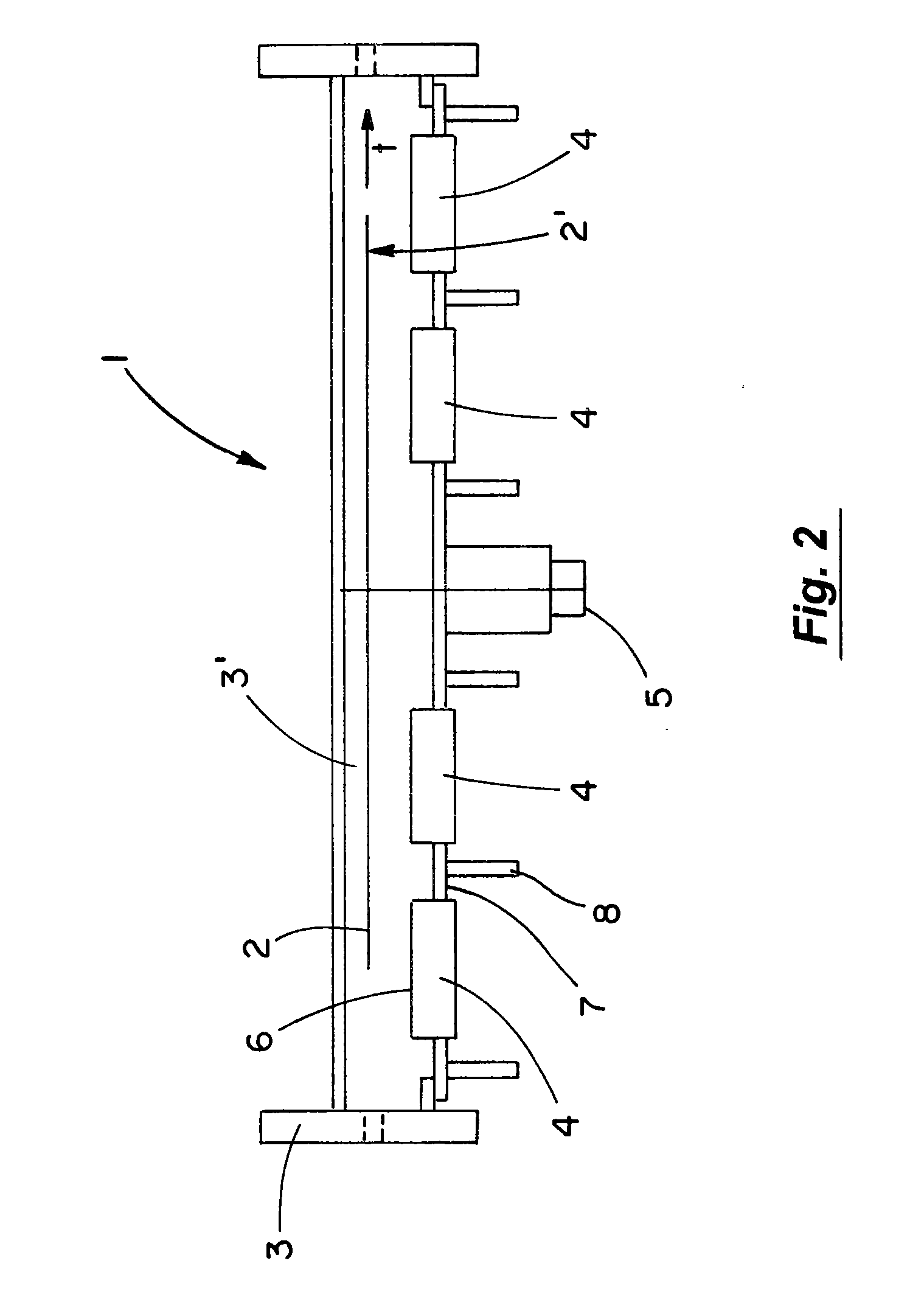
A sputter coating installation 1 comprises a vacuum chamber having an interior space 3′. The interior space 3′ of the vacuum chamber is defined by chamber walls 3. According to the present invention, an array of target units 9 is arranged in line inside the vacuum coating chamber. Particularly, the target units 9 are arranged tiltable relative to the vacuum chamber and relative to a transport path t of a substrate 2. The target units 9 are cathode units or magnetron units and comprise a target and a housing. The housing is attached to the target and defines an interior space of the target unit. Within the interior space of the target units a number of components are arranged, e.g. a combination of a magnet yoke and a magnet system, a magnet yoke drive, a cooling system (arranged near the target), an electric current supply for supplying energy for the sputter process, etc. The combination of the magnet yoke and the magnet system is movable on a linear path to perform a reciprocating movement relative to the target during the operation of the target unit. Outside the housing a vacuum pressure pv is generated vacuum pumps 5 arranged in a chamber wall 3c of the vacuum chamber behind the target units 9 for enabling the sputter coating process. In the interior space of the housing another pressure p may prevail, particularly a considerably higher pressure p. For example, the pressure p in the interior space of the housing may be an atmospheric pressure. Therefore, the housing provides a vacuum sealing of the interior space of the housing relative to the outside of the housing.

Description

TECHNICAL FIELD[0001]The present invention concerns a sputter coating device, comprising at least one coating chamber, and at least a first target unit arranged inside said coating chamber, wherein said target unit comprises at least one substantially planar sputter target.PRIOR ART[0002]Sputtering is a well-known technology for depositing films of various materials on a substrate. In a static sputter coating process the substrate is positioned opposite a target while being coated. In a dynamic sputter coating process the substrate is transported continuously past a plurality of sputter targets during the coating process.[0003]In conventional vacuum coating installations rotatable magnetrons and planar magnetrons are used. Rotatable magnetrons comprise a rotatable cylindrical target and a magnet system positioned inside the target. Planar magnetrons have a substantially planar target surface and a magnet system moveably positioned behind the target. A plurality of magnetrons may be ...

Claims


Application Information

Patent Timeline
Patent Type & Authority Applications(United States)
IPC IPC(8): C23C14/35
CPCC23C14/352C23C14/562H01J37/3455H01J37/3414H01J37/3423H01J37/3405
Inventor LOPP, ANDREASLINDENBERG, RALPH
Owner APPLIED MATERIALS INC
Why Eureka
Try Eureka