C-arm mounted on a robotic arm

a robotic arm and c-arm technology, applied in the field of xray devices, can solve problems such as correspondingly complex constructions, and achieve the effects of simple assembly and accessibility, convenient manufacturing, and convenient operation

Active Publication Date: 2009-07-16
SIEMENS HEALTHCARE GMBH
View PDF14 Cites 12 Cited by
  • Summary
  • Abstract
  • Description
  • Claims
  • Application Information

AI Technical Summary

Benefits of technology

[0010]The interior of the C-arm may be accessible from access sides, which are arranged opposite to one another. For example, the access sides may be the two side surfaces in the case of a rectangular arm profile, as viewed from the cross-section. The relevant positions on both sides may be reached for assembly or maintenance purposes, thereby facilitating operation. As a result, assembly and accessibility is simple.
[0011]The C-arm may be a framework on one access side. For example, struts may be arranged in the form of a framework on one access side. The framework may be applied to both sides in the case of an arm structure, which is open on both sides. The framework construction may be realized on both sides, which may include the same configuration. The C-arm may be a cast part. As a result, the C-arm may be easily manufactured. The embodiment of the framework structure and / or the arrangement of the struts is selected on the one hand in respect of weight optimization, in order to save as much material as possible. The strut arrangement is designed in order to achieve the desired mechanical properties. Material may be saved primarily in the region of low mechanical stresses and / or loads, whereas in regions of a higher mechanical load, corresponding supports are provided in a suitable angular arrangement in respect of each other and / or other arm sections. The design of the structure conforms with the given geometric and mechanical specifications.

Problems solved by technology

This results in correspondingly complex constructions.

Method used


Image

  • C-arm mounted on a robotic arm
  • C-arm mounted on a robotic arm
  • C-arm mounted on a robotic arm

Examples


Embodiment Construction

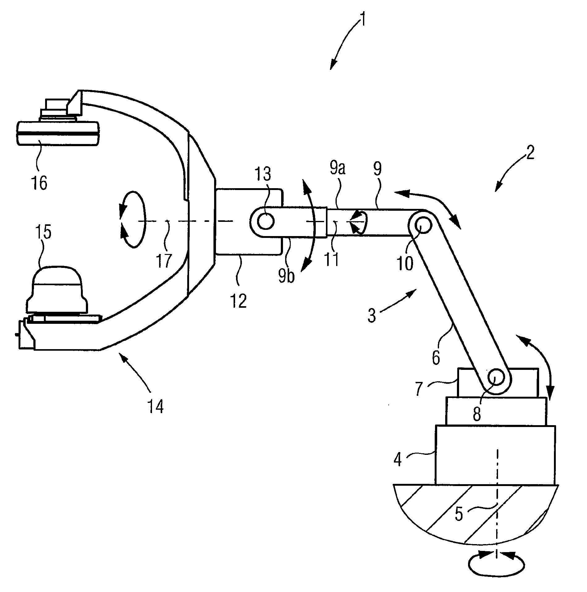
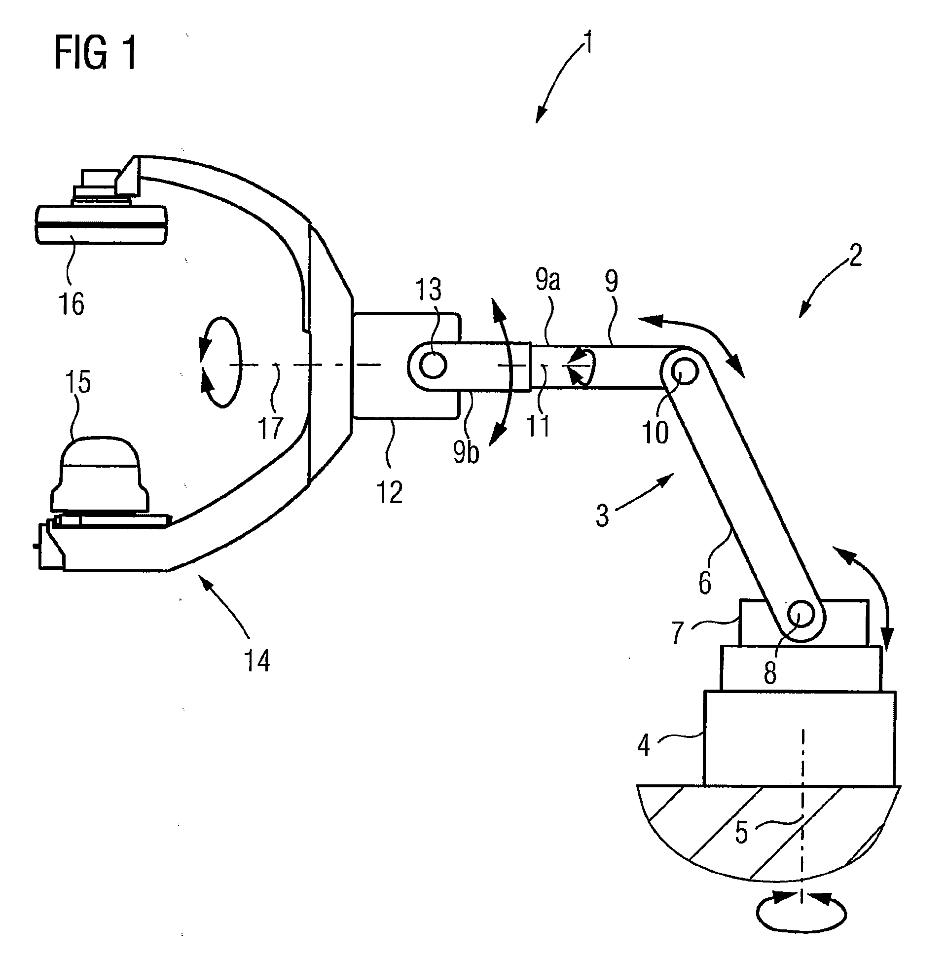
[0022]FIG. 1 shows an x-ray device 1 including an industrial robot 2, with a robotic arm 3, which is accommodated on a base 4, arranged on the floor. The robotic arm 3 is rotatable overall on the base about a vertical axis 5. The robotic arm 3 is accommodated on the base 4 by a first robotic arm 6 on a base part 7. The first robotic arm 6 can be rotated about the vertical axis, on which base part 7 it can also be pivoted about a horizontal axis 8. A second robotic arm 9 is positioned on the first robotic arm 6. The robotic arm 9 may be pivotable thereupon about a second horizontal axis 10. The second robotic arm 9 includes the first arm section 9a, which is arranged on the first robotic arm 6, as well as a second arm section 9b, which for its part can be rotated about a further axis 11 relative to the arm section 9a. A C-arm mount 12, which can be rotated about the axis 13, may be positioned on the arm section 9b. The C-arm 14, upon which a radiation source 15 and a radiation detect...


PUM


Abstract

An x-ray device is provided. The x-ray device includes a C-arm that may be rotatably mounted on a robotic arm. A radiation source and a radiation detector may be arranged on the C-arm. The interior of the C-arm, which is hollow at least in sections, is accessible from at least one access side to allow at least a part of the electronic components used to operate the radiation source and the radiation detector to be integrated in the interior of the arm.

Description

[0001]This patent document claims the benefit of DE 10 2008 003 816.4, filed Jan. 10, 2008, which is hereby incorporated by reference.BACKGROUND[0002]The present embodiments relate to an x-ray device including a C-arm rotatably mounted on a robotic arm.[0003]X-ray devices include a C-arm that is rotatably arranged on an upright stand on the floor by a swivel guide about a conventionally horizontal axis. In the swivel guide, the C-arm is rotatable about an isocenter along the curved swivel guide. A light C-arm is used in order to achieve as effective a dynamic as possible, especially when the C-arm is moved along the swivel guide at considerable speed. For example, an angiography x-ray device may include a C-arm that is moved along the swivel guide at considerable speed. As a result, C-arms made of extruded profiles that have an essentially rectangular hollow profile cross-section are normally used.[0004]The C-arm may be arranged on a robotic arm. Instead of a floor stand with the sw...

Claims


Application Information

Patent Timeline
Patent Type & Authority Applications(United States)
IPC IPC(8): H01J31/50H05G1/02
CPCA61B6/4458A61B6/4441
Inventor GROSS, STEFANHEINL, DIETER
Owner SIEMENS HEALTHCARE GMBH
Why Eureka
Try Eureka