Fixing device and image forming apparatus including the same

a technology of fixing device and image forming apparatus, which is applied in the direction of ohmic resistance heating, electrographic process apparatus, instruments, etc., can solve the problems of long warm-up time, high power consumption, and very low heat conductivity of the layer, and achieve excellent heat efficiency, short warm-up time, and less power consumption

Active Publication Date: 2009-07-16
SHARP KK
View PDF6 Cites 4 Cited by
  • Summary
  • Abstract
  • Description
  • Claims
  • Application Information

AI Technical Summary

Benefits of technology

[0019]A first object of the present invention is to provide (I) a fixing device (i) using a planar heat-generating belt type fixing method, which provides a short warm-up time, and (ii) being arranged so as to be excellent in heat efficiency, to consume less power, and not to allow a fixing belt to slip easily, and (II) an image forming apparatus including the fixing device. A second object of the present invention is to provide (I) the fixing device arranged so as to shorten first copy output time and (II) an image forming apparatus including the fixing device.

Problems solved by technology

Increasing the thickness of the elastic layer, however, causes the following problem: In a case where the fixing roller internally includes the heating means as in a conventional arrangement, the fixing roller including the elastic layer having an increased thickness does not increase its temperature according to an increased processing speed, because the elastic layer has a very low heat conductivity.
Further, increasing the diameter of the fixing roller causes such a problem that (i) warm-up time is extended and (ii) much power is consumed.
These fixing devices using the conventional planar heat-generating belt type fixing method, however, have the following problems.
Therefore, the arrangement of Patent Document 2 has a problem with heat efficiency.
The problem is caused as follows: Heat is emitted, to atmosphere, from an inner surface area of the fixing belt which area is not in contact with the planar heat-generating body or the fixing roller, and thereby the heat efficiency is decreased.
Further, the arrangement of Patent Document 2 has a problem of slippage of the fixing belt.
The problem is caused as follows: the deformed shape of the fixing belt wound around the fixing roller causes friction force to be applied to the fixing belt when the fixing belt slides on the heating member, and thereby the fixing belt becomes more prone to slip.
Therefore, when printing operation is started immediately after the stand-by mode, heat of the fixing belt is rapidly taken away by the fixing roller, and thereby a degree of undershooting is increased.
This arises such a problem that FCOT (First Copy Output Time) is extended.
However, with the arrangement where the heating member is provided so as to be far from the fixing roller, it is impossible to sufficiently reduce the heat loss and thereby to improve the belt running performance.
However, with the arrangement where the heating member provided so as to be far from the fixing roller, it is impossible to sufficiently pre-heat a fixing roller having a large heat capacity.

Method used


Image

  • Fixing device and image forming apparatus including the same
  • Fixing device and image forming apparatus including the same
  • Fixing device and image forming apparatus including the same

Examples


first embodiment

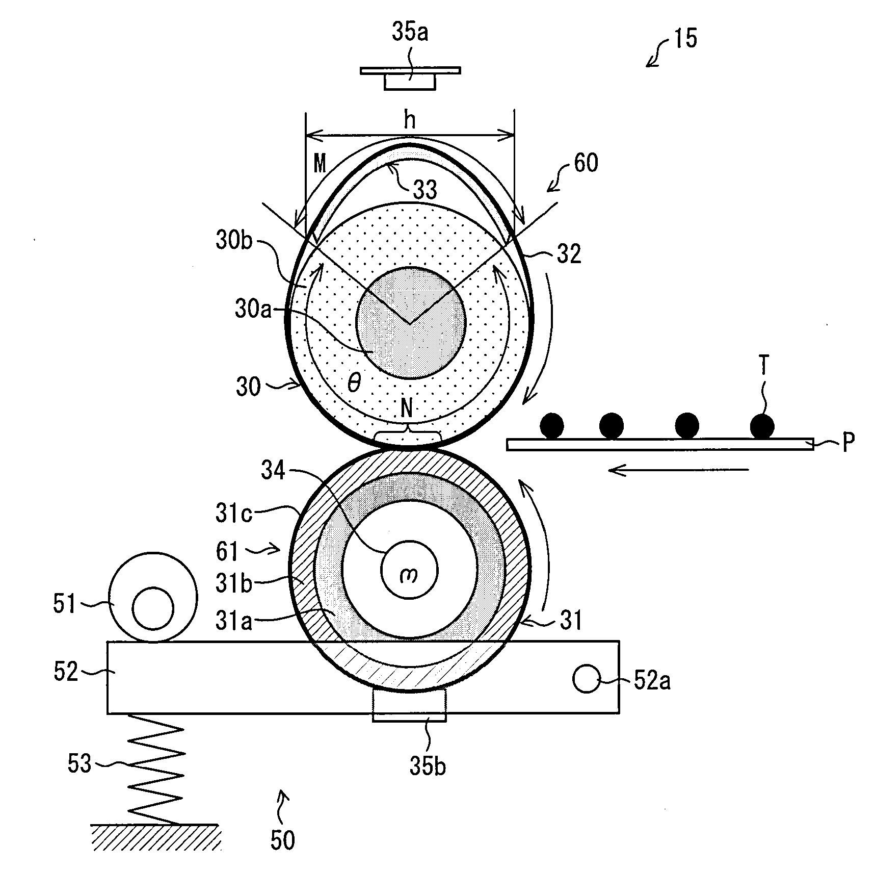
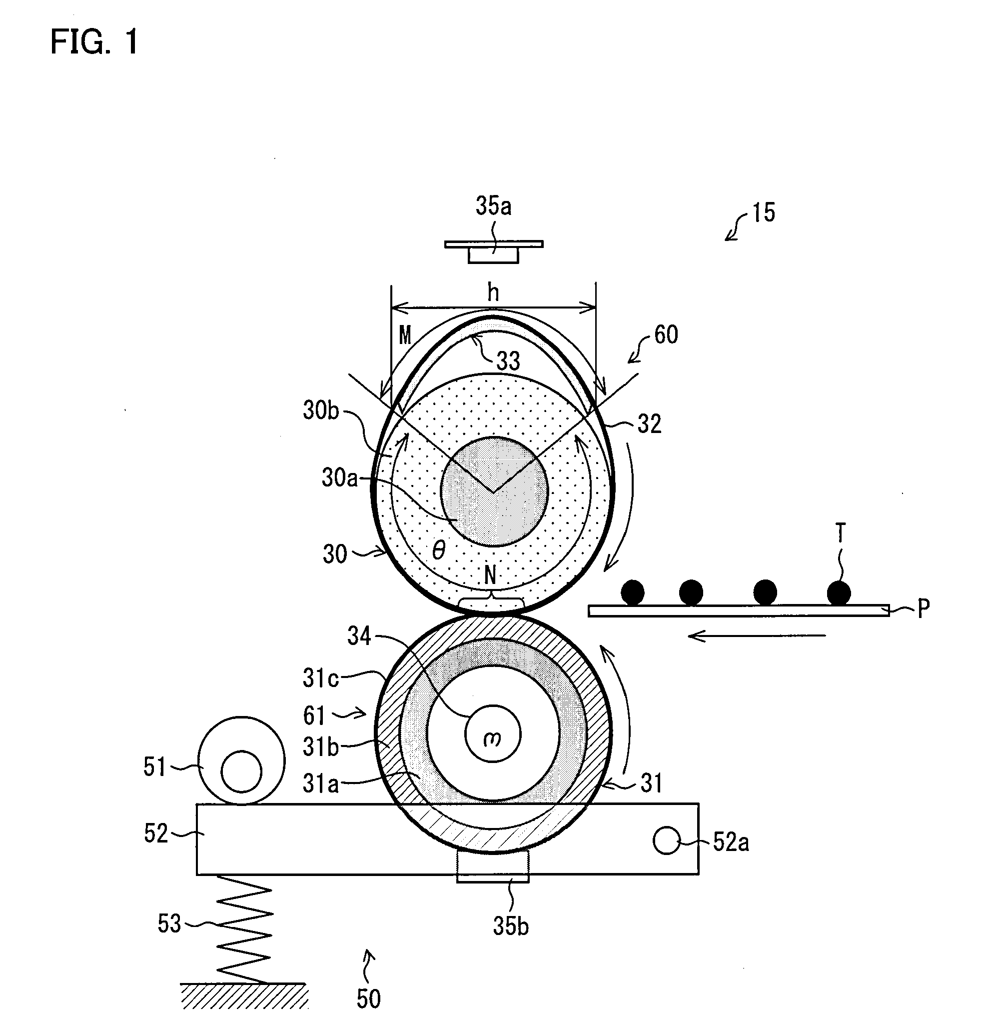
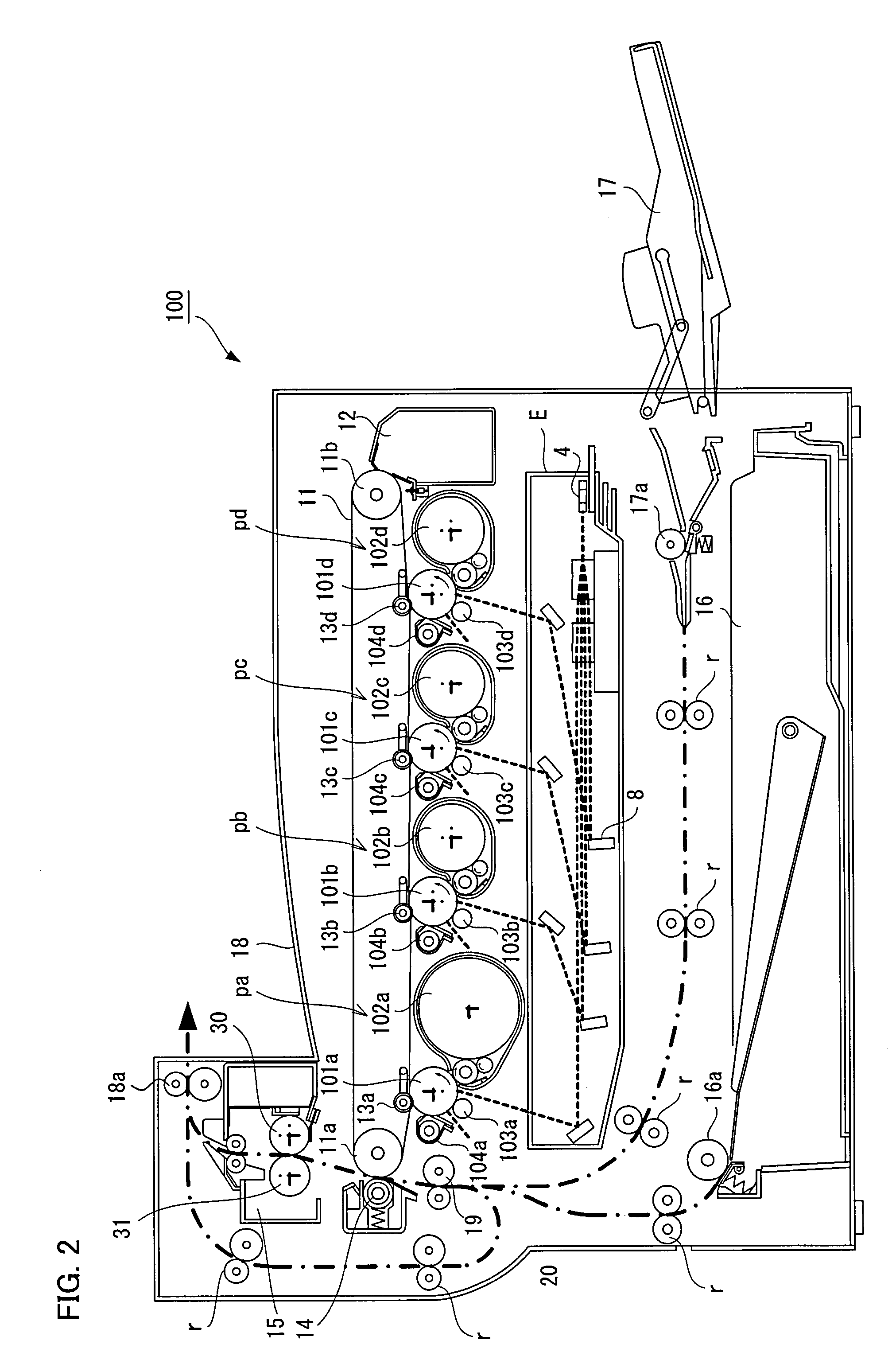
[0037]The following describes, with reference to FIG. 1 through FIG. 4, one embodiment of the present invention. The present embodiment is arranged such that a fixing device and an image forming apparatus each of which is of the present invention are used in a color multifunction peripheral. FIG. 1 is a cross-section view illustrating an arrangement of a fixing unit (a fixing device) included in the color multifunctional peripheral, as viewed in an axial direction; FIG. 2 is a schematic view illustrating an arrangement of the color multifunction peripheral; FIG. 3 is an enlarged view illustrating an arrangement of a cross-section of a planar heat-generating member (heating member) made out of a planar heat-generating body; and FIG. 4 is a front view of a planar heat-generating member.

[0038]A color multifunction peripheral 100 according to the present embodiment includes, as illustrated in FIG. 2, an optical system unit E, four visual image forming units pa, pb, pc, and pd, an interm...

second embodiment

[0077]The following describes, with reference to FIG. 5, another embodiment of the present invention. A fixing unit 40 of Second Embodiment has the same structure as that of the fixing unit 15 of First Embodiment. However, the fixing unit 40 is different from the fixing unit 15 in the way that the fixing unit 40 includes a fixing section 62 instead of the fixing section 60. Therefore, for convenience of description, members having the same functions as those explained in First Embodiment are given the same signs as First Embodiment, and descriptions thereof are omitted here. Further, the description of the same structure as that explained in First Embodiment is omitted here.

[0078]As illustrated in FIG. 5, the fixing section 62 differs from the fixing section 60, in a planar heat-generating member 42 and a fixing belt 41. Except for them, the fixing section 62 has the same structure as that of the fixing section 60. As illustrated in FIG. 5, the planar heat-generating member 42 in th...

third embodiment

[0084]The following describes, with reference to FIG. 6, further another embodiment of the present invention. A fixing unit 43 of Third Embodiment has the same structure as that of the fixing unit 40 of Second Embodiment. However, the fixing unit 43 is different from the fixing unit 40 in the way that the fixing unit 43 includes a pressure section 63 having the same structure as that of the fixing section 62, instead of the fixing section 61 including the pressure roller 31 and the heater lamp 34. Therefore, for convenience of description, members having the same functions as those explained in First Embodiment and Second Embodiment are given the same signs as First Embodiment and Second Embodiment, and descriptions thereof are omitted here. Further, the description of the same structure as that explained in First Embodiment and Second Embodiment is omitted here.

[0085]The pressure section 63 in the fixing unit 43 of Third Embodiment has the same structure as that of the fixing secti...


PUM


Abstract

A fixing device of the present invention is arranged so that: (i) at least both ends of a planar heat-generating member come close to or touch an outer surface of a fixing roller, said both ends being in a circumferential direction when viewed in an axial direction of the fixing roller; and (ii) the planar heat-generating member has, in the vicinity of both the ends, shapes formed gently with respect to the outer surface of the fixing roller when viewed in the axial direction. An almost whole inner surface area of the fixing belt wound around the planar heat-generating member and the fixing roller touches the planar heat-generating member or the fixing roller. The fixing belt is naturally formed, without being distorted at an area where the fixing belt touches the heating member. This allows a fixing device using a planar heat-generating belt type fixing method, which provides a short warm-up time, to be excellent in heat efficiency, consume less power, and have a fixing belt which does not slip easily.

Description

[0001]This Nonprovisional application claims priority under 35 U.S.C. §119(a) on Patent Application No. 006214 / 2008 filed in Japan on Jan. 15, 2008, the entire contents of which are hereby incorporated by reference.FIELD OF THE INVENTION[0002]The present invention relates to (I) a fixing device which is included in an image forming apparatus using an electrophotographic printing method and (II) an image forming apparatus including the fixing device.BACKGROUND OF THE INVENTION[0003]As a fixing device used in an image forming apparatus (e.g., a copying machine and a printer) using an electrophotographic printing method, a fixing device using a heat-roller fixing method is widely used. The fixing device using the heat-roller fixing method includes a pair of rollers (a fixing roller and a pressure roller) which press each other. Further, both or either one of the pair of rollers internally includes heating means containing a halogen heater or the like. The fixing device fixes a toner im...

Claims


Application Information

Patent Timeline
Patent Type & Authority Applications(United States)
IPC IPC(8): G03G15/20
CPCG03G2215/2025G03G15/2053
Inventor KAGAWA, TOSHIAKI
Owner SHARP KK
Why Eureka
Try Eureka