Particle concentration measurement technology

a technology of concentration measurement and particle, applied in the field of particle concentration measurement technology, can solve the problems of small particles, particle sizes less than 50 nm can significantly reduce the manufacturing yield of present-day semiconductor devices, and the manufacturing industry of semiconductor devices, so as to achieve higher kinetic energy mixing, reduce the effect of particle size and particle siz

Active Publication Date: 2009-07-23
CT ASSOCS
View PDF6 Cites 32 Cited by
  • Summary
  • Abstract
  • Description
  • Claims
  • Application Information

AI Technical Summary

Benefits of technology

[0022]In contrast to other nebulizers in which the chamber exit is simply open to the downstream components with a diameter equal to that of the chamber, the exit orifice in the nebulizer in D has a diameter less than that of the chamber, more preferably less than half the diameter chamber. The diameter reduction provides a constriction that produces a higher kinetic energy mixing of the gas and liquid in the merger zone. As a result, the nebulizer generates smaller droplets. The secondary orifice also helps direct the aerosol toward the impactor surface raising the impactor efficiency.
[0023]Another factor reducing the droplet size produced by the atomizer/impactor is close axial positioning of an impactor just downstream of the secondary orifice. The more closely spaced impactor removes a greater proportion of the larger droplets.
[0024]In a preferred version of nebulizer/impactor, the impactor axial spacing from the secondary orifice is adjustable through movement of the impactor. For example, a threade...

Problems solved by technology

Small particles are a major problem for the semiconductor device manufacturing industry.
Particles smaller than 50 nm can significantly reduce manufacturing yield of present day semiconductor devices.
Insofar as is known, there is no technology to meet this need.
Instruments capable of measuring particles of these sizes are not believed to be available.
The problem is that below about 300 nm the amount of light scattered by a particle is proportional to the 6th power of the diameter (DP6).
Particle Measurement Systems had a counter with a claimed sensitivity of 30 nm counter on the market at one time, but it is no longer available.
High purity liquids typically have low con...

Method used


Image

  • Particle concentration measurement technology
  • Particle concentration measurement technology
  • Particle concentration measurement technology

Examples


Embodiment Construction

[0052]The present invention provides a method and apparatus for determining the size distribution and concentration of particles in a liquid.

[0053]A. Methods of the Invention.

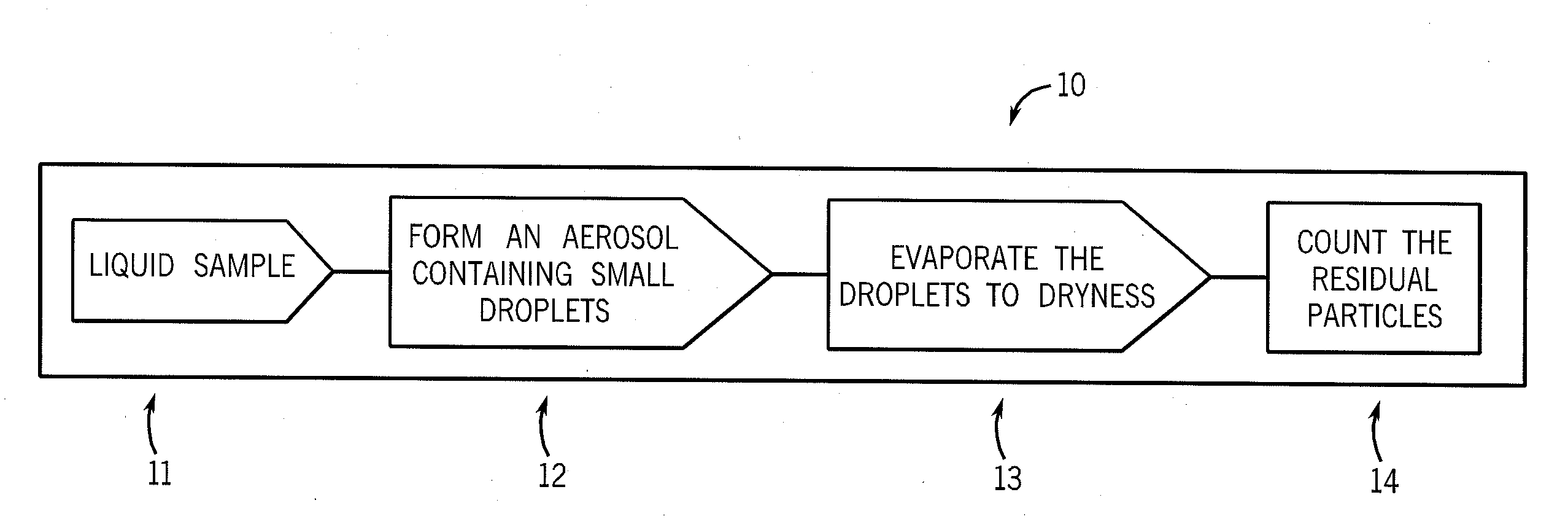
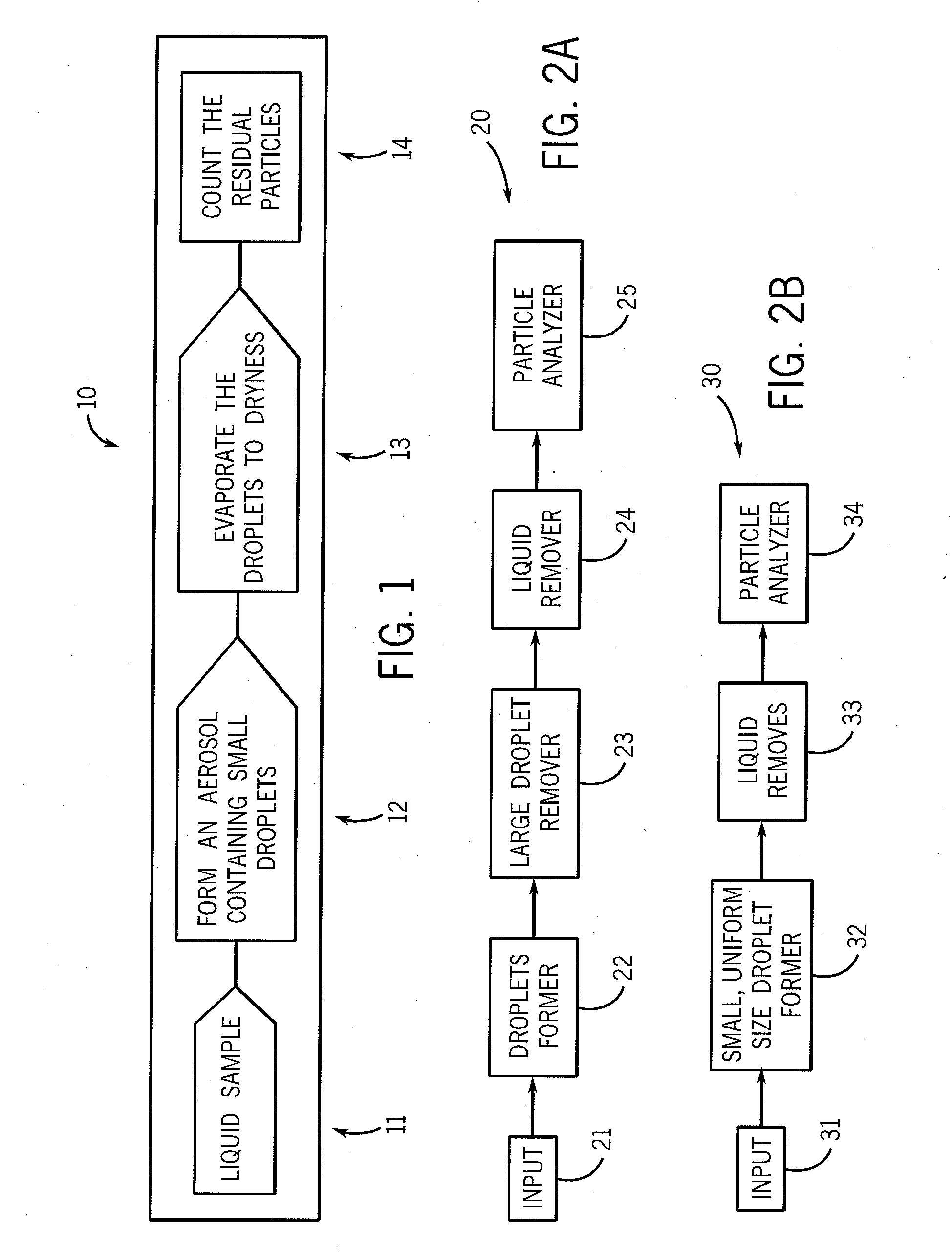
[0054]The method involves (a) forming droplets, for example via aerosolization, from a liquid sample to be analyzed, (b) isolating small droplets from the droplets, for example less than 10 um in size, (c) drying the droplets to remove the liquid, for example via evaporation, and (d) counting the residual particles.

[0055]Importantly, the aerosol droplets isolated are small and uniformly sized, less than 10 um and preferably a median size less than 1 um. The droplets must be small and uniformly sized because any dissolved material in the droplet will form a “residue” particle as a result of drying. If the residue particle is large enough it will be detected by the analyzer and interfere with the measurement of true, non-dissolved, particles.

[0056]The size of a residue particle resulting from evaporation of a liq...


PUM


Abstract

A method and apparatus for measuring particle concentration and size distribution of particles in liquids. The method involve separating dissolved and particulate residues in liquids for determination of the size and concentration of the particulate species. The method includes the steps of forming an aerosol from the liquid sample to be analyzed, evaporating the droplets in the aerosol to dryness, and detecting the particles. An apparatus for separating dissolved and particulate residues in liquids for determination of the size and concentration of the particulate species is also disclosed. The apparatus includes a droplet former, a dryer communicatively connected to the droplet former, and a detector communicatively connected to the evaporator for detecting particles.

Description

CROSS-REFERENCE TO RELATED APPLICATIONS, IF ANY[0001]This application claims the benefit under 35 U.S.C. §119(e) of co-pending U.S. Provisional Patent Application Ser. No. 61 / 011,901, filed Jan. 22, 2008, which is hereby incorporated by reference.STATEMENT REGARDING FEDERALLY SPONSORED RESEARCH OR DEVELOPMENT[0002]Not applicable.REFERENCE TO A MICROFICHE APPENDIX, IF ANY[0003]Not applicable.BACKGROUND[0004]1. Field[0005]The present invention relates, generally, to analysis methods and apparatus for use with compositions of matter. More particularly, the invention relates to a method and apparatus for measuring the size and concentration of small particles in high purity liquids and colloidal suspensions. Most particularly, the invention relates to an apparatus and method for separating dissolved and particulate residues in a liquid to determine the size distribution and concentration of the particulate species (i.e. particles). The technology is useful, for example, for accurate mea...

Claims


Application Information

Patent Timeline
IPC IPC(8): G01N15/06G01N1/22
CPCG01N1/4022G01N1/44G01N2001/2223G01N2001/4027G01N15/0255G01N15/065G01N2015/0038G01N15/0205G01N15/0266
Inventor GRANT, DONALD C.LITCHY, MARK R.BLACKFORD, DAVID
Owner CT ASSOCS
Why Eureka
Try Eureka