Measuring Analyte Concentrations in Liquids

a technology of analyte concentration and liquid, which is applied in the direction of instruments, combustible gas purification/modification, separation processes, etc., can solve the problems of limiting the utility of analyte concentration detection and measurement, lack of sensitivity sufficient for detecting and measuring extremely low analyte concentration, and bubble formation, etc., to achieve a smaller droplet size, reduce the size of the droplet, and increase the kinetic energy mixing

Inactive Publication Date: 2008-06-12
TSI INC
View PDF10 Cites 67 Cited by
  • Summary
  • Abstract
  • Description
  • Claims
  • Application Information

AI Technical Summary

Benefits of technology

[0032]In contrast to previous nebulizers in which the chamber exit is simply open to the downstream components with a diameter equal to that of the chamber, the exit orifice in the present nebulizer has a diameter less than that of the chamber, and more preferably less than half the chamber diameter. The diameter reduction provides a constriction which produces a higher kinetic energy mixing of the gas and separator eluent in the merger zone. As a result, the nebulizer generates smaller droplets. The secondary orifice also helps direct the aerosol towards the impactor raising the impactor efficiency
[0033]Another factor reducing droplet size is a close axial positioning of an impactor, just downstream of the secondary orifice. The more closely spaced impactor removes a greater proportion of the larger droplets, reducing baseline concentration (noise) for improved dynamic range in generating analyte concentration data.
[0034]In a preferred version of the nebulizer, the impactor axial spacing from the secondary orifice is adjustable through movement of the impactor. For example, a threaded mounting of the impactor to the nebulizer frame allows axial position adjustment by turning the impactor about its longitudinal axis. The average size of droplets in the aerosol leaving the nebulizer can be increased or decreased by respectively enlarging or reducing the axial spacing between the secondary orifice and the impactor.
[0035]The droplet size also can be adjusted by changing or selecting the secondary orifice. Reducing the diameter of the secondary orifice is believed to increase back pressure and reduce droplet size. It has been found useful to provide a secondary orifice with a diameter larger than that of the primary orifice. The ratio of the secondary orifice diameter to the primary orifice diameter can range from slightly above one, to about two in versions that incorporate a secondary orifice.

Problems solved by technology

While the systems are well suited for a variety of applications, they are subject to difficulties that limit their utility.
One of these is the lack of sensitivity sufficient for detecting and measuring extremely low analyte concentrations.
Another difficulty concerns bubble formation due to gasses dissolved in the water or other liquid entering the nebulizer.
The bubbles eventually break free and tend to disrupt residue concentration measurements downstream of the nebulizer.
A further system problem, relating to the condensation particle counter, concerns the use of butyl alcohol or similar fluids with low vapor mass diffusivity for growing the residue particles into droplets.
Such liquids tend to be flammable, toxic, and produce noxious odors.
Frequently they are subject to health and environmental regulations that restrict their use in indoor environments.
Another persistent problem, due to relatively long fluid flow paths within and between the nebulizer and CPC, is the relatively long time elapsed between a change in the concentrations of analytes in a given liquid sample, and the detection of the change.
The longer paths allow more time for axial diffusion, which ultimately has a negative impact on the instrument response.
Another difficulty with conventional condensation particle counters is the limited dynamic range typical of many CPC designs, due primarily to the increase in coincidence events that accompanies increased particle concentration.

Method used


Image

  • Measuring Analyte Concentrations in Liquids
  • Measuring Analyte Concentrations in Liquids
  • Measuring Analyte Concentrations in Liquids

Examples


Embodiment Construction

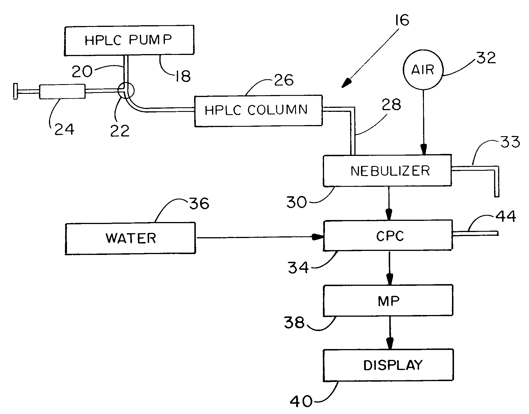
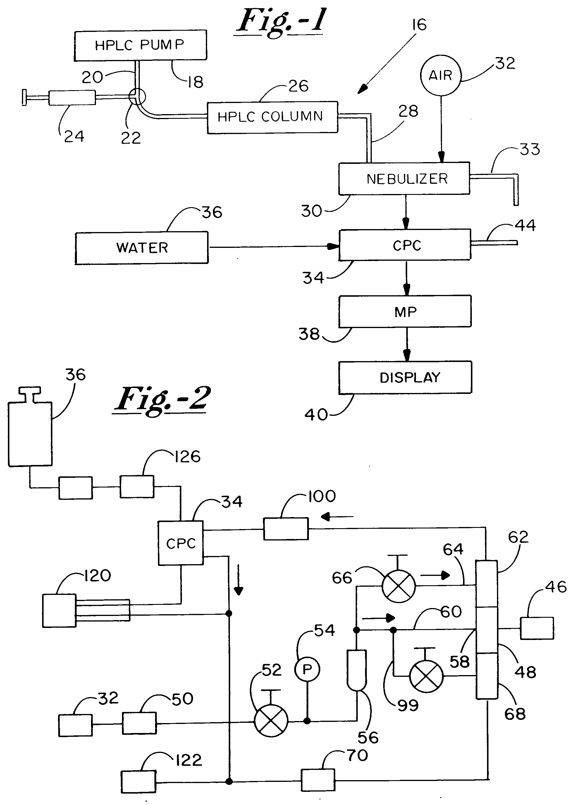
[0053]Turning now to the drawings, there is shown in FIG. 1 a diagram of a high performance liquid chromatography (HPLC) system 16 for identifying and measuring concentrations of non-volatile residue constituents dissolved in water or another liquid. The system includes a high performance liquid chromatography pump 18 for supplying water or another solvent as a carrier liquid (mobile phase) through a conduit 20 at a predetermined constant flow rate, e.g. 1 milliliter per minute. An injection valve 22 along conduit 20 is coupled to a syringe 24 containing a liquid sample and operable in stepped fashion to introduce substantially instantaneous injections of the liquid sample into the carrier liquid stream. The injections do not undergo any substantial mixing with the carrier liquid, but instead form plugs of the liquid sample that remain substantially separate from the carrier liquid. The liquid sample includes a base liquid such as water, acetonitrile (CH3CN), or alcohols, along with...


PUM

PropertyMeasurementUnit
pressureaaaaaaaaaa
temperatureaaaaaaaaaa
diameteraaaaaaaaaa

Abstract

A high performance liquid chromatography system employs a nebulizer with a flow restriction at the exit of its mixing chamber to produce finer droplets, and an adjustable impactor for increased control over droplet sizes. Downstream of the mixing chamber, the nebulizer can incorporate tubing that is permeable to the sample liquid, to promote aerosol drying through perevaporation. A condensation particle counter downstream of the nebulizer uses water as the working medium, and is adjustable to control threshold nucleation sizes and droplet growth rates. A particle size selector employing diffusion, electrostatic attraction or selection based on electrical mobility, is advantageously positioned between the nebulizer and the CPC.

Description

[0001]This application claims the benefit of priority based on Provisional Patent Application No. 60 / 857,609, entitled “System for Separating Non-volatile Analytes and Measuring Analyte Concentrations,” filed Nov. 7, 2006.BACKGROUND OF THE INVENTION[0002]The present invention relates to systems for measuring minute concentrations of constituents dissolved in liquids, and more particularly to systems that employ analyte separation and aerosol generation to distinguish constituents and measure their concentrations.[0003]A variety of instruments are used for identifying and measuring concentrations of solutes in liquid media. Separators can employ any one of several analyte separation techniques, e.g. liquid chromatography, high performance liquid chromatography (normal or reversed phase), ion exchange chromatography and gel permeation chromatography. Analyte separation involves moving liquid and dissolved constituents, known as the mobile phase, through a stationary phase, e.g. a stai...

Claims


Application Information

Patent Timeline
Patent Type & Authority Applications(United States)
IPC IPC(8): G01N1/00B01D47/00G01N30/00
CPCG01N15/065G01N2030/8447G01N30/84
Inventor OBERREIT, DEREK R.QUANT, FREDERICK R.BLACKFORD, DAVID B.
Owner TSI INC
Why Eureka
Try Eureka