Non-aqueous electrolyte battery and method for producing the same

a non-aqueous electrolyte and battery technology, applied in the direction of cell components, final product manufacturing, sustainable manufacturing/processing, etc., can solve the problems of lowering production efficiency, lowering productivity, complicated mold structure of upper and lower case molds, etc., to facilitate the lowering of battery internal pressure, improve battery strength, and improve battery strength

Active Publication Date: 2009-07-23
MURATA MFG CO LTD
View PDF3 Cites 88 Cited by
  • Summary
  • Abstract
  • Description
  • Claims
  • Application Information

AI Technical Summary

Benefits of technology

[0035]In an embodiment, the resin material contains therein a fiber material from the viewpoint of improving the battery strength. The method may further includes, after the step for covering the battery element, winding a fiber material around the battery element covered with the film-form casing member. In this case, with respect to the fiber material, continuous fiber, a woven fabric formed by weaving continuous fiber, or a non-woven fabric formed from short fiber is preferably used. When continuous fiber is used, in an embodiment, the continuous fiber is wound uniformly in a predetermined fiber di

Problems solved by technology

When the upper case and lower case are fixed to each other using a fitting nail, a space for the nail must be formed in the upper case and lower case, causing the structures of the molds for the upper case and lower case to be complicated.
When the upper case and lower case are fixed to each other using a screw, a boss space is needed, and a step for turning a screw is required, which leads to a lowering of the production efficiency.
When the cases are bonded together by welding using an organic solvent, the amount of the solvent applied varies to cause the bonding force to be non-uniform, which leads to a lowering of the pro

Method used


Image

  • Non-aqueous electrolyte battery and method for producing the same
  • Non-aqueous electrolyte battery and method for producing the same
  • Non-aqueous electrolyte battery and method for producing the same

Examples


first embodiment

(1) First Embodiment

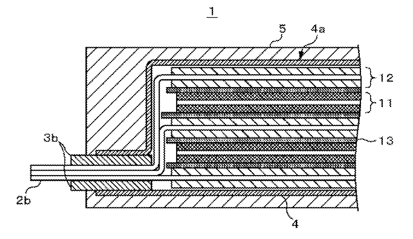
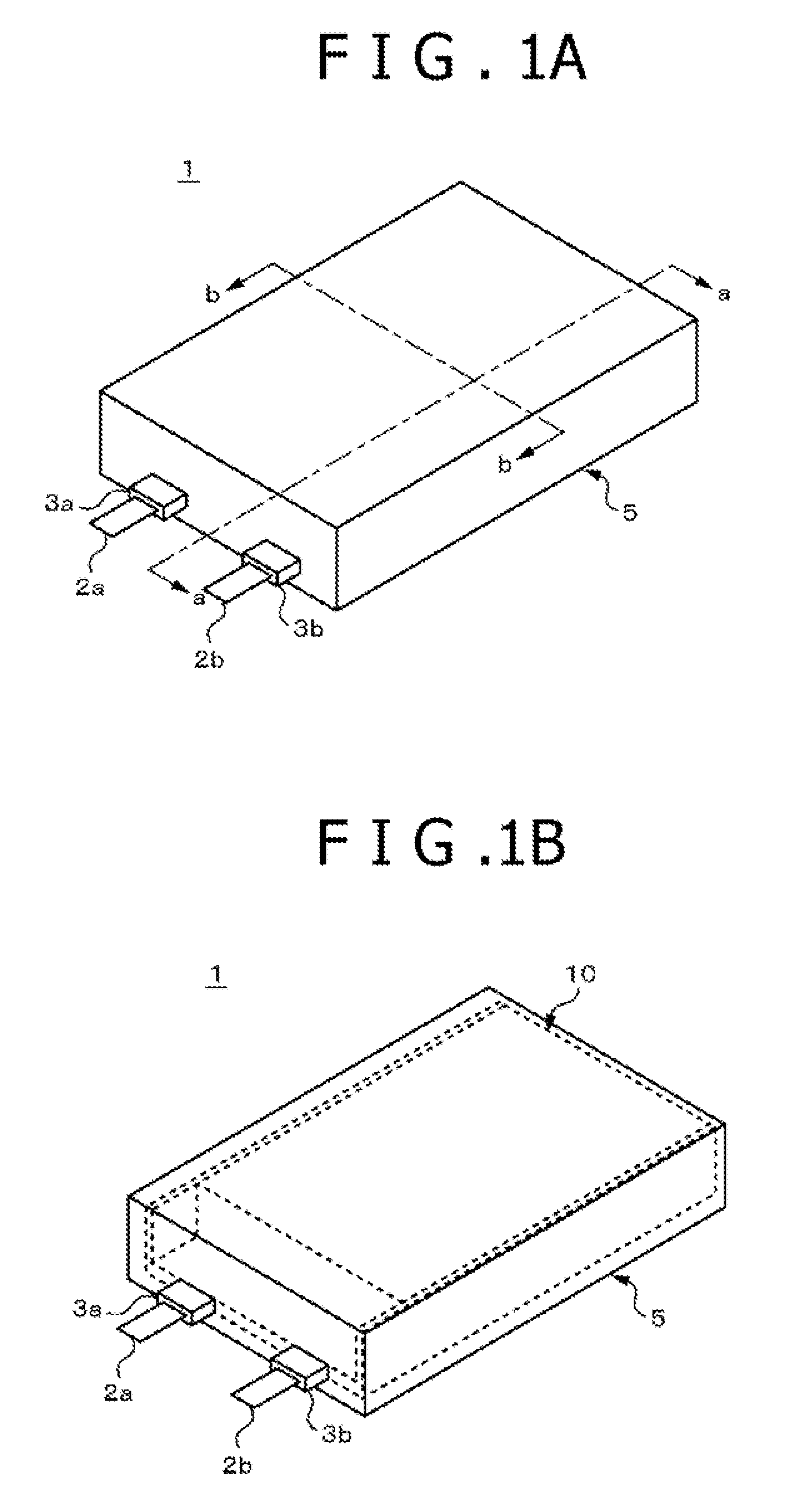
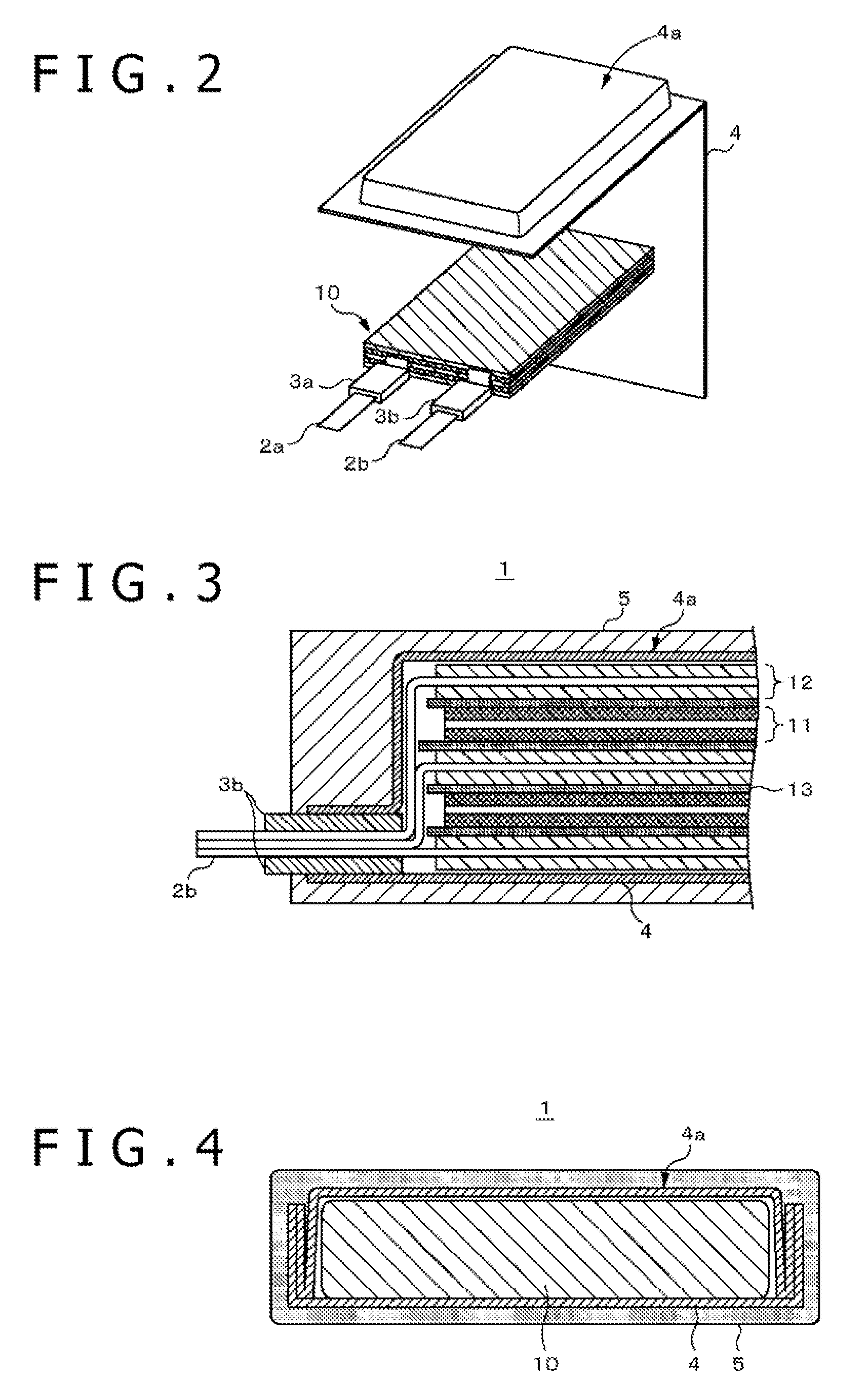
[0057]Hereinbelow, a first embodiment will be described with reference to the accompanying drawings. In the first embodiment, a non-aqueous electrolyte battery having a battery element covered with a metal laminated film as a casing member material and having a resin protective layer formed around the laminated film is described.

[0058]In the present specification, frequently, a lead side for the positive electrode terminal and negative electrode terminal in the non-aqueous electrolyte battery is referred to as “top portion”, a side opposite to the top portion is referred to as “bottom portion”, and a side portion disposed between the top portion and the bottom portion is referred to as “side portion”. The non-aqueous electrolyte battery using a battery element having a stacked structure is described below, but the present application is not limited to this, and can be applied to any thin battery element having a spirally wound structure, a zigzag folded structure...

second embodiment

(2) Second Embodiment

[0113]Hereinbelow, a second embodiment will be described with reference to the accompanying drawings. Generally, when a battery is, for example, in an overcharged state, the battery temperature is increased to cause decomposition of the electrolytic solution and the like, thus generating gas in the battery, so that the pressure in the battery rises. In the second embodiment, a secondary battery having improved safety when the pressure in the battery rises is described.

(2-1) Construction of Non-Aqueous Electrolyte Battery

[0114]FIG. 12A is a diagrammatic view showing an example of the appearance of a secondary battery 20 according to the second embodiment, and FIG. 12B is a diagrammatic view showing an example of the construction of the secondary battery 20. The secondary battery 20 includes a resin protective layer 5 for improving the battery strength, and further has an opening forming portion 25a such that a sealing portion of the laminated film 4 is opened whe...

example 1

Sample 1-1

Preparation of Positive Electrode

[0127]90 Parts by mass of lithium cobaltate (LiCoO2) as a cathode active material, 5 parts by mass of acetylene black as a conductor, and 5 parts by mass of polyvinylidene fluoride (PVdF) as a binder were uniformly mixed with each other to prepare a positive electrode composition, and the anode mixture prepared was dispersed in N-methyl-2-pyrrolidone to form an anode mixture slurry. The resultant anode mixture slurry was uniformly applied to both sides of an aluminum (Al) foil as a negative electrode current collector, and subjected to vacuum drying at 100° C. for 24 hours, followed by pressure molding by means of a roll pressing machine, to form a cathode active material layer. Subsequently, a positive electrode terminal made of aluminum (Al) was connected to a portion of the positive electrode current collector at one end on which the cathode active material layer was not formed.

Preparation of Negative Electrode

[0128]90 Parts by mass of ...


PUM


Abstract

A non-aqueous electrolyte battery includes a battery element, a film-form casing member, and a resin protective layer. The battery element includes a positive electrode, a negative electrode, and a separator disposed between the positive electrode and the negative electrode. The film-form casing member contains the battery element and an electrolyte in an enclosed space thereof. The resin protective layer is formed along the surface of the film-form casing member and has a substantially uniform thickness.

Description

CROSS-REFERENCE TO RELATED APPLICATIONS[0001]The present application claims priority to Japanese patent Application No. 2008-12589 filed in the Japanese Patent Office on Jan. 23, 2008, the entire disclosures of which is incorporated herein by reference.BACKGROUND[0002]The present application relates to a non-aqueous electrolyte battery and a method for producing a non-aqueous electrolyte battery. More particularly, the present application relates to a non-aqueous electrolyte battery having high strength and providing a satisfactory safety and a method for producing a non-aqueous electrolyte battery.[0003]In recent years, various types of portable electronic devices, such as camera-integrated video tape recorders (VTRs), cell phones, and laptop computers, come on the market, and those having smaller size and weight are being developed. As the portable electronic devices are reduced in size and weight, demand for battery as a power source of them is rapidly increasing, and, for reduci...

Claims


Application Information

Patent Timeline
IPC IPC(8): H01M2/02H01M2/08H01M6/00H01M50/119H01M50/121H01M50/124H01M50/133H01M50/178H01M50/529
CPCH01M2/0267H01M2/0275H01M2/0277H01M10/0585H01M2/0295H01M2/06H01M10/052H01M2/0287Y02E60/10H01M50/124Y02P70/50H01M50/133H01M50/121H01M50/178H01M50/119H01M10/058H01M10/0525
Inventor HARADA, TAMOTSUNARUSE, YOSHIAKIISHIGOOKA, TAKASHIOHYAGI, NOBUYUKI
Owner MURATA MFG CO LTD
Why Eureka
Try Eureka