Biochip cartridge

a technology of biochips and cartridges, applied in the field of biochip cartridges, can solve the problems of increased testing cost, increased risk, and increased risk of operator being infected with a virus, and achieve the effect of preventing the danger of the operator accidentally coming into contact and low self-fluorescen

Inactive Publication Date: 2009-07-23
YOKOGAWA ELECTRIC CORP
View PDF12 Cites 5 Cited by
  • Summary
  • Abstract
  • Description
  • Claims
  • Application Information

AI Technical Summary

Benefits of technology

[0039]It is an object of the present invention to solve the abovementioned problems by using an elastic body for the substrate member in order to stabilize the feeding of blood or solution and providing a biochip cartridge capable of preventing the danger of the operator accidentally coming into contact with solution due to mishandling.
[0040]It is another object of the present invention to realize a biochip cartridge that is low self-fluorescence.
[0041]It is yet another object of the present invention to provide a biochip cartridge that allows pre-processing and cleaning to be performed within the cartridge and hybridized biopolymers to be detected using a general-purpose reader.

Problems solved by technology

In contrast, the method of introducing a solution shown in FIG. 3 involves the risk of the operator being infected with a virus, such as HIV, as a result of accidental contact with the solution due to mishandling.
This risk exists because the method always involves transferring the solution from solution infusion means 14 to cartridge 11.
Another problem with the conventional biochip is that the cost of testing increases since more than one kind of medical equipment must be disposed of, including syringes, appliances used for preprocessing purposes, injection means, DNA chips, and so on.
Although such a biochip cartridge as described above is advantageous in that processes, including blood collection, preprocessing and hybridization, are performed consistently and automatically, the cartridge requires a rigid blood collection tube and is therefore expensive.
Furthermore, the biochip cartridge involves using an air suction pump or the like to produce negative pressure, and thus overall costs are comparatively high.
(1) Blood collection bag 41 is squeezed unevenly when being pinched and forwarded by rollers 61 and 62, thus hindering the flow of blood or stabilization of solution.
(2) Since blood collection bag 41 is soft, self-fluorescence tends to occur easily due to the adhesive agent, coatings or plastic materials used therein. This self-fluorescence constitutes background noise and causes the S / N ratio to change. Consequently, it becomes infeasible to detect weak fluorescent light (signal) emitted from the fluorescent substance with which DNA has been marked.
(3) It is not possible to store mRNA or DNA as is, without submitting it to hybridization, nor is it possible to make already-stored mRNA or DNA undergo hybridization only.
(4) Although the biochip in question is designed so that pre-processing and hybridization are performed within the bag and, therefore, is advantageous in that it can eliminate the risk of viruses, for example, being released from the biochip during processing, the biochip has the problem that it is not possible to use a general-purpose, slide glass type DNA microarray. Note that although there is a cassette capable of hybridization using a general-purpose, slide glass type DNA microarray, the cassette requires conversion of the sample into cDNA or labeling the sample (for example, attaching fluorescent markers) in a laboratory or other places. Furthermore, use of the cassette involves post-hybridization cleaning, resulting in the problem that a specific place and special skills are required.
(5) Such a dedicated biochip as illustrated in FIG. 1 requires the use of a dedicated reader suited for that biochip, resulting in the problem that it is not possible to use general-purpose readers.

Method used


Image

  • Biochip cartridge
  • Biochip cartridge
  • Biochip cartridge

Examples


Embodiment Construction

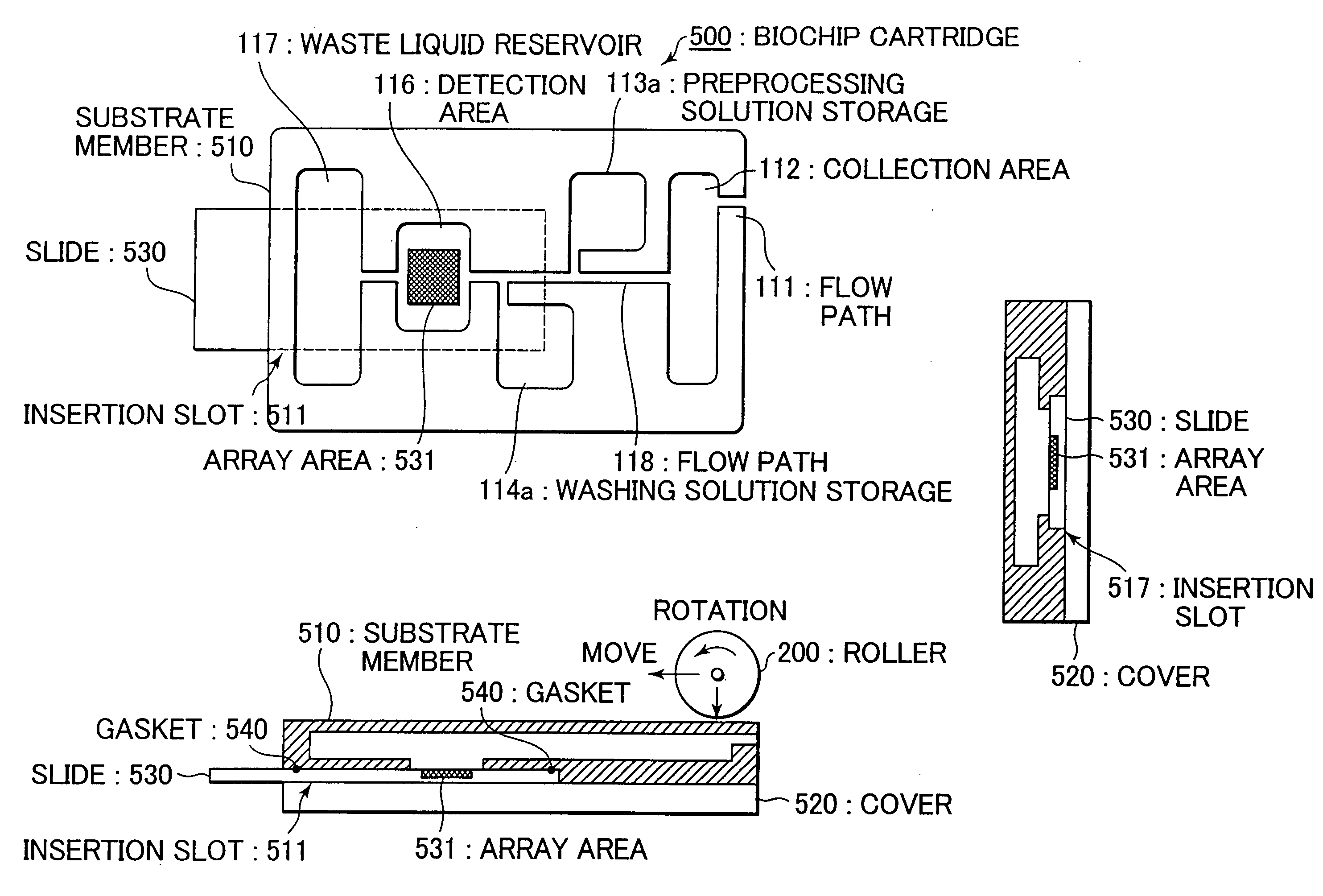
[0065]Preferred embodiments are described in detail hereinafter by referring to the accompanying drawings, wherein FIG. 7 is a schematic view illustrating one embodiment of the biochip cartridge in accordance with the present invention. FIG. 7(a) is a side view, FIG. 7 (b) is the plan view of a substrate member, and FIG. 7(c) is the view of section A-A′ (including covers).

[0066]In biochip cartridge 100 illustrated in FIG. 7(a), symbols 101 and 102 indicate transparent and flexible covers made from hard plastics and symbol 110 indicates a substrate member formed using an elastic body, such as airtight, elastic rubber. Covers 101 and 102 are hermetically attached onto the top and bottom surfaces of substrate member 110 by means of, for example, adhesion.

[0067]Formed on substrate member 110 are a through-hole for flow path 111 at the inlet of the substrate member, a plurality of chambers, i.e., collection area 112, first and second pockets 113 and 114, preprocessing area 115, detection...


PUM

PropertyMeasurementUnit
sizeaaaaaaaaaa
sizeaaaaaaaaaa
sizeaaaaaaaaaa

Abstract

The present invention provides a biochip cartridge wherein an elastic body is used for a substrate member in order to stabilize the feeding of blood or solution and whereby it is possible to avoid the risk of accidental contact of the operator with solutions due to mishandling.
The biochip cartridge comprises a tabular substrate member formed using an elastic material and a flexible cover airtightly attached to the surface of the substrate member, wherein at least an area for storing biopolymers, an area for detecting desired biopolymers from the biopolymers that have been preprocessed, and a flow path for connecting the areas is formed on the substrate member, so that biopolymers can be successively moved from the biopolymer storage area to the biopolymer detection area through the flow path.

Description

[0001]This application is a continuation application of U.S. Ser. No. 10 / 716,417, filed Nov. 20, 2003, which claims priority of Japanese Patent Application Nos. 2003-002813 filed on Jan. 9, 2003, 2003-010486 filed on Jan. 20, 2003, and 2003-010487 filed on Jan. 20, 2003, respectively, each of which are hereby incorporated by reference in their entirety.BACKGROUND OF THE INVENTION[0002]1. Field of the Invention[0003]The present invention relates to a biochip cartridge for use with biochips intended to test biopolymers, such as DNA, RNA (mRNA or cDNA, for example) and protein and, more particularly, to a biochip cartridge that is extremely safe and can reduce the cost of testing.[0004]2. Description of the Prior Art[0005]Biochip cartridges for testing DNA or other biopolymers have been well known. For example, a biochip cartridge (also simply referred to as biochip) used to read the sequence of a DNA target by scanning a hybridized DNA chip with a biochip reader as illustrated in FIG....

Claims


Application Information

Patent Timeline
Patent Type & Authority Applications(United States)
IPC IPC(8): C12M1/00B01L3/00G01N21/11G01N21/64G01N33/543G01N35/00
CPCB01L3/502715B01L3/50273B01L3/502738B01L3/505B01L2200/0689B01L2200/10B01L2300/0636B01L2300/0816B01L2300/0822B01L2300/0867B01L2300/087B01L2400/0481B01L2400/0683G01N21/11G01N21/64G01N33/54386G01N2035/00158
Inventor TANAAMI, TAKEOFUKUSHIMA, KAZUHISA
Owner YOKOGAWA ELECTRIC CORP
Why Eureka
Try Eureka