RF ablation device with jam-preventing electrical coupling member

a technology of electrical coupling and ablation device, which is applied in the field of rf ablation device with jam-preventing electrical coupling member, can solve the problems of loose bundles of thermocouple wires and inability to move freely, and achieve the effects of reducing the likelihood of unintentional actuation, removing potential loss of information, and facilitating information provision

Active Publication Date: 2009-07-23
ACESSA HEALTH INC +1
View PDF99 Cites 10 Cited by
  • Summary
  • Abstract
  • Description
  • Claims
  • Application Information

AI Technical Summary

Benefits of technology

[0027]Optionally, the electrical switches which operate the system may be recessed partially or fully in order to minimize the likelihood of unintentional actuation. Additional protection may be provided by requiring two motions within a relatively short period of time in order to achieve a change in the control of the system.
[0028]In accordance with a particularly preferred version of the invention, this is achieved by having a human v

Problems solved by technology

Thus, the thermocouple wires are not loosely bundled and are not free to move within a slidable operator which typically moves up

Method used


Image

  • RF ablation device with jam-preventing electrical coupling member
  • RF ablation device with jam-preventing electrical coupling member
  • RF ablation device with jam-preventing electrical coupling member

Examples


Embodiment Construction

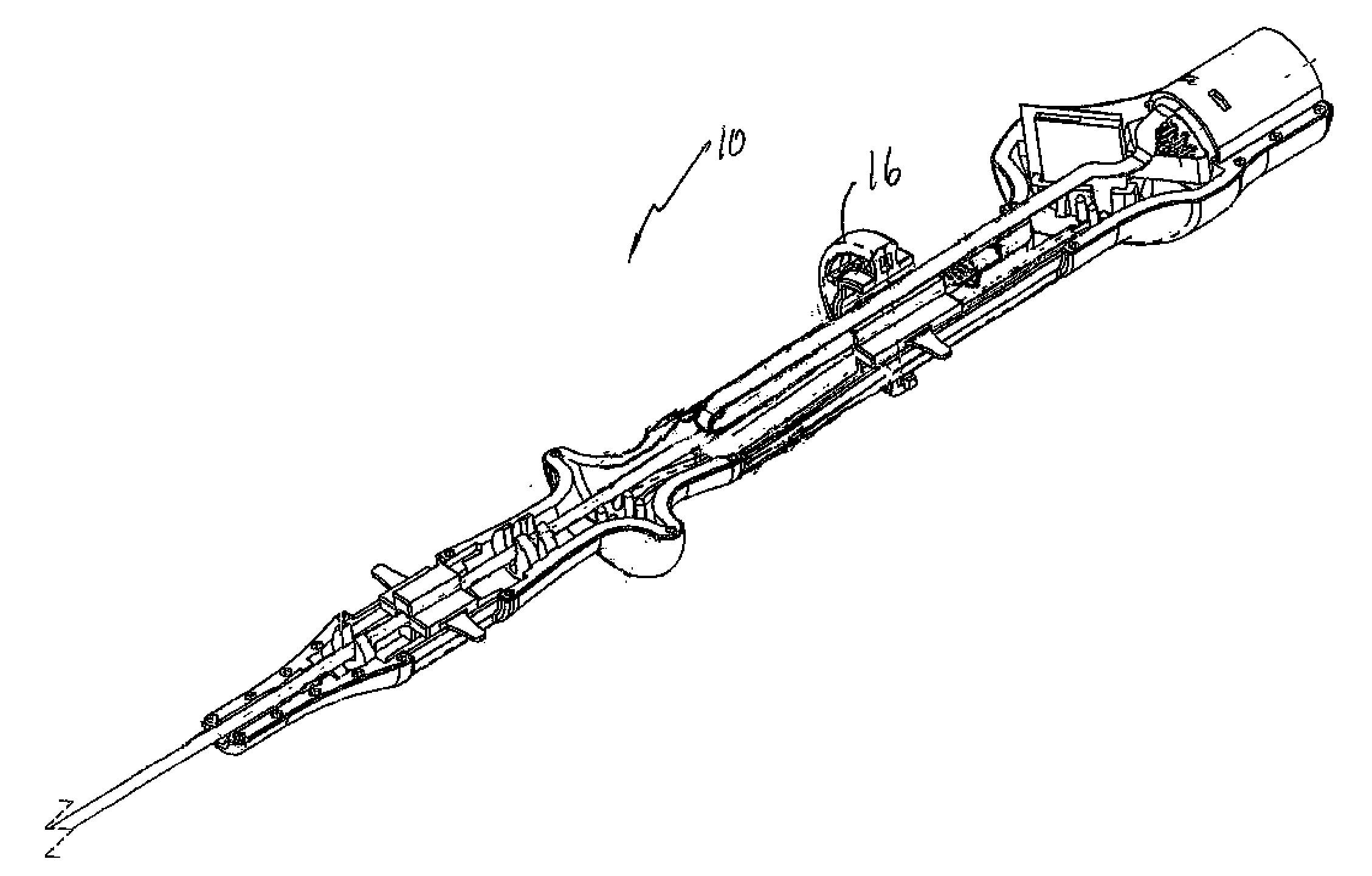
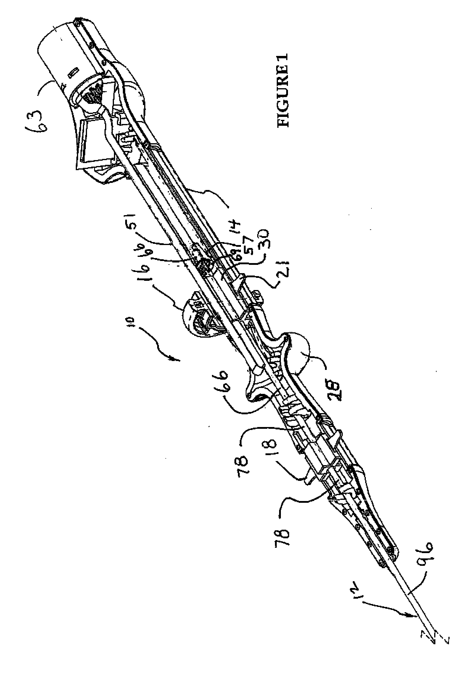
[0061]Referring to FIG. 1, an ablation instrument 10 constructed in accordance with the present invention is illustrated. Instrument 10 comprises a catheter portion 12 and a handle portion 14. Ablation instrument 10 is illustrated with one of the two mating handle halves 28 removed, in order to reveal its internal parts and workings in connection with the following description.

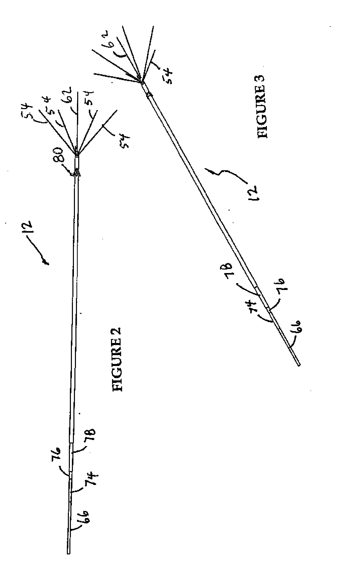
[0062]Referring to FIGS. 1, 2 and 3, the inventive ablation instrument 10 is illustrated in the fully forward ablation position, which the instrument takes after full advancement of stylets 54 into tissue, for example, tissue to be subjected to ablation by being treated with radiofrequency energy. In this position, the trocar 32 with its point 34 provide catheter 12 with a simple thin smooth pointed surface well-suited to penetrate healthy tissue while doing minimal damage. At the same time, the sharpness of the point and the relatively stiff, though somewhat flexible, nature of catheter 12 enables accurate st...


PUM


Abstract

The inventive ablation element comprises an elongated cannula having a proximal end and a distal end. The cannula defines an internal lumen within the cannula and a cannula axis. A plurality of conductors contained within the lumen, each of the conductors has a proximal end proximate the proximal end of the cannula, and a distal end proximate the distal end of the cannula. A plurality of ablation stylets each has a proximal end and a distal end, and each coupled at the respective proximal end of the stylet to the distal end of a respective conductor, the stylets comprise a deflectable material, the conductors together with their respective stylets being mounted for axial movement. A trocar point defined proximate the distal end of the cannula. A deflection surface positioned between the trocar point and the proximal end of the cannula, the deflection surface being configured and positioned to deflect, in response to axial movement of the stylets in a direction from the proximate end of the cannula to the distal end of the cannula, at least some of the stylets laterally with respect to the cannula axis in different directions along substantially straight paths, the paths defining an ablation volume.

Description

CROSS REFERENCE TO RELATED APPLICATION[0001]Not ApplicableBACKGROUND[0002]In the United States, approximately 230,000 women have hysterectomies annually. The primary reason for performing a hysterectomy is the presence of uterine fibroids. These fibroids grow in the wall of the uterus and may range in size up to several inches across. In the United States alone, there are more than six million women with uterine fibroid symptoms who prefer to suffer, rather than endure the risks and inconveniences associated with major surgery, especially a major surgery that results in infertility. Outside of the United States, the situation is much the same, with millions of women suffering with fibroids in need of a safe alternative to hysterectomy.[0003]Recently, another treatment option (uterine artery embolization) has been introduced. Generally, this procedure involves embolization of the arteries which feed the urine fibroid. This results in cutting off the blood supply to the fibroid and th...

Claims


Application Information

Patent Timeline
IPC IPC(8): A61B18/18
CPCA61B18/1477A61B2017/00101A61N1/06A61B2018/1475A61B2018/143
Inventor EPSTEIN, GORDONLEE, BRUCECOHEN, JEFFREY M.HAGMANN, ADAMSPERO, RICHARD
Owner ACESSA HEALTH INC
Why Eureka
Try Eureka