Ion radiation therapy system with variable beam resolution

a radiation therapy system and beam resolution technology, applied in the field of radiation therapy systems, can solve the problems of inconvenient construction of compensators, inconvenient use, and inconvenient use, and achieve the effect of small dose features and precise delineation of edges

Active Publication Date: 2009-07-30
WISCONSIN ALUMNI RES FOUND
View PDF52 Cites 119 Cited by
  • Summary
  • Abstract
  • Description
  • Claims
  • Application Information

AI Technical Summary

Benefits of technology

[0008]The present invention provides a radiotherapy system usable with ion beams that uses multiple beam spot sizes to effect a precise trade-off between treatment speed and accuracy. For example, spatially larger beams may be used to treat large relatively homogenous portions of the treatment area with smaller beams providing precise delineation of edges and small dose features.

Problems solved by technology

Further, the dose deposited by a proton beam is not uniform along the entrance path of the beam, but rises substantially to a “Bragg peak” near a point where the proton beam stops within the tissue.
This treatment approach essentially treats the entire tumor at once and, thus, is fast and yet less precise and requires the construction of a special compensator.
This approach is potentially very accurate, but because the tumor is treated in successive exposures, is slower than the first approach.
Further the small spot sizes create the risk of uneven dose placement or “cold spots” should there be patient movement between exposures.

Method used


Image

  • Ion radiation therapy system with variable beam resolution
  • Ion radiation therapy system with variable beam resolution
  • Ion radiation therapy system with variable beam resolution

Examples


Embodiment Construction

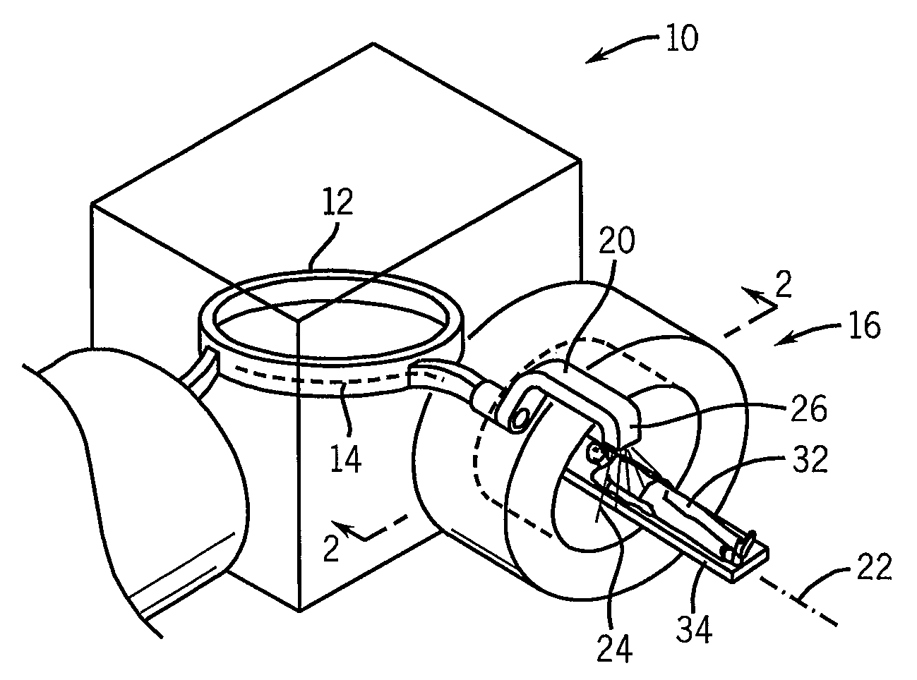
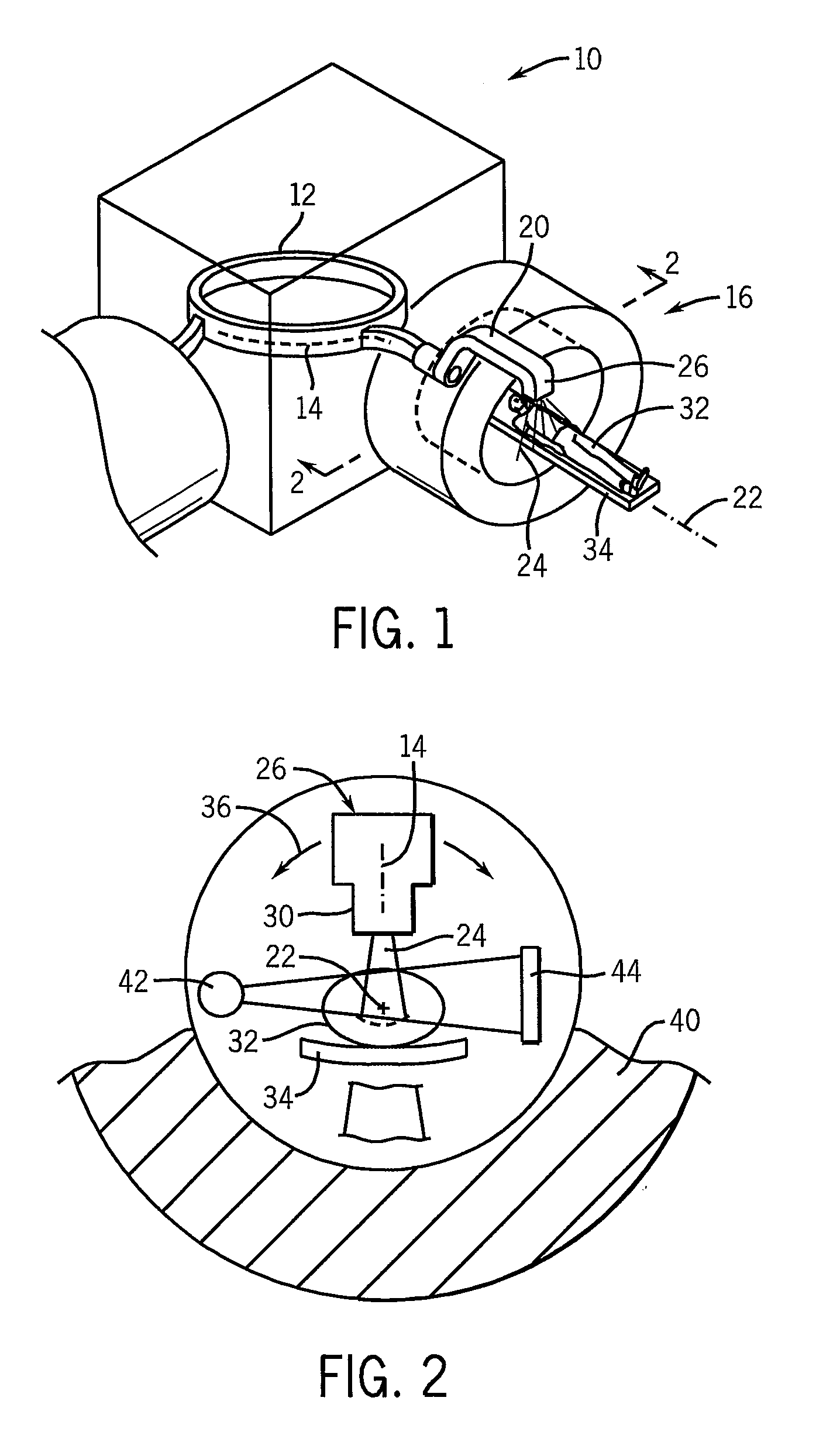
[0049]Referring now to FIGS. 1 and 2, an ion therapy system 10 may include a cyclotron or synchrotron 12 or other ion source providing a pencil beam 14 of ions that may be directed to a gantry unit 16. The pencil beam 14 may be received at the gantry unit 16 along an axis 22 into an axial portion of a rotating arm 20 rotating about the axis 22. The rotating arm 20 incorporates guiding magnet assemblies of a type known in the art to bend the pencil beam 14 radially away from the axis 22 then parallel to the axis and spaced from the axis 22 to be received by a treatment head 26. The treatment head 26 orbits about the axis 22 with rotation of the rotating arm 20 and incorporates magnets bending the ion pencil beam 14 back toward the axis 22 to intersect the axis perpendicularly.

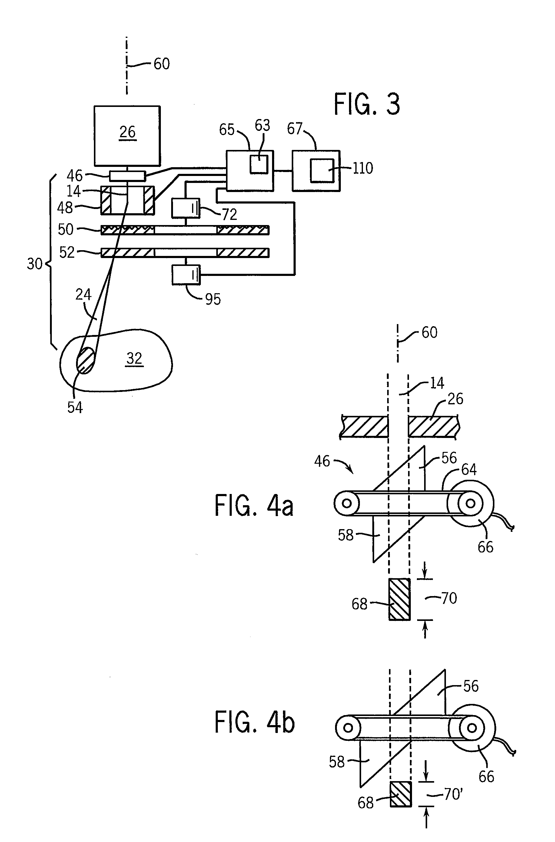
[0050]As will be described in more detail below, the treatment head 26 may include a modulation assembly 30 to produce a variable resolution treatment beam 24. A patient 32 may be positioned on a support table 3...


PUM


Abstract

An ion radiation therapy machine provides a steerable beam for treating a tumor within the patient where the exposure spot of the beam is controlled in width and / or length to effect a flexible trade-off between treatment speed, accuracy, and uniformity.

Description

CROSS-REFERENCE TO RELATED APPLICATIONS[0001]This application claims the benefit of U.S. Provisional Application 60 / 891,859, filed Feb. 27, 2007, and PCT Application PCT / US2008 / 055096, filed Feb. 27, 2008, the disclosures of which are incorporated herein by reference.STATEMENT REGARDING FEDERALLY SPONSORED RESEARCH OR DEVELOPMENT[0002]This invention was made with United States government support awarded by the following agency: NIH CA088960. The United States government has certain rights in this invention.BACKGROUND OF THE INVENTION[0003]The present invention relates to radiotherapy systems using ions (such as protons) for the treatment of cancer and the like and, in particular, to a system providing improved treatment speed and accuracy.[0004]External beam radiation therapy may treat a tumor within the patient by directing high-energy radiation in one or more beams toward the tumor. Recent advanced external beam radiation systems, for example, as manufactured by Tomotherapy, Inc.,...

Claims


Application Information

Patent Timeline
Patent Type & Authority Applications(United States)
IPC IPC(8): A61N5/00G21K1/00
CPCA61N5/10A61N2005/1095A61N2005/1087A61N5/103
Inventor FLYNN, RYAN THOMASMACKIE, THOMAS R.
Owner WISCONSIN ALUMNI RES FOUND
Why Eureka
Try Eureka