
Method and arrangement for controlling an electric drive

a technology of electric drive and arrangement, which is applied in the direction of electronic commutation motor control, motor/generator/converter stopper, dynamo-electric converter control, etc., can solve the problems of insufficient speed and reaction time of relay, and achieve the effect of sufficient braking torque and avoiding safety-critical situations

Inactive Publication Date: 2009-07-30
ZF FRIEDRICHSHAFEN AG
View PDF8 Cites 0 Cited by
  • Summary
  • Abstract
  • Description
  • Claims
  • Application Information

AI Technical Summary

Benefits of technology

The patent proposes a method for controlling an electric drive in case of a fault. The motor control unit initiates a safety measure to switch to a secure operating condition in case of a fault detection. This includes a fault-associated operating mode that allows a direct current to be fed to the motor, via the remaining phases, to maintain the motor in a condition that avoids a safety-critical situation. The technical effect of this method is to ensure the motor remains operational in case of a fault, thereby improving safety and reliability.

Problems solved by technology

However, it has been shown that in view of the high dynamics of the electric motor drive, the reaction time of the relay, is not sufficiently rapid to provide a guarantee that the drive can be changed to a secure or fail-safe condition.

Method used


Image

  • Method and arrangement for controlling an electric drive
  • Method and arrangement for controlling an electric drive

Examples


Embodiment Construction

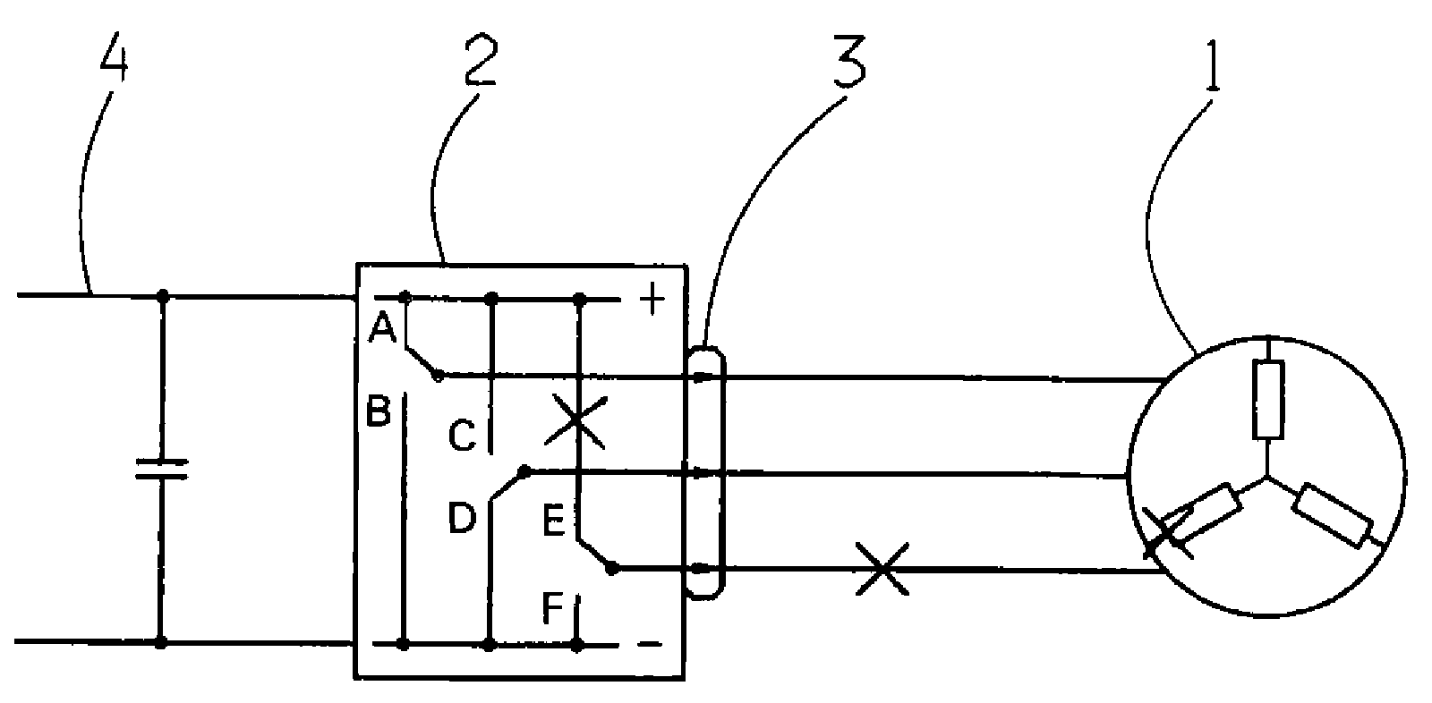
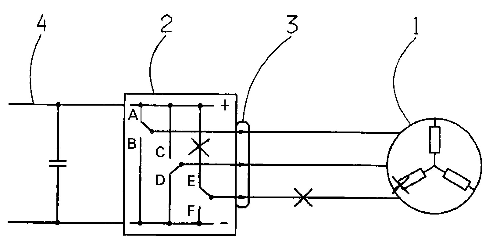
[0015]The drive comprises a synchronous motor 1 which can be controlled by a motor control unit. The motor control unit comprises at least a power output stage or a power electronic stage 2. The power electronic stage 2 is supplied with energy from a main power system 4 or an intermediate network. The power electronic stage 2 comprises a bridge circuit (B6), indicated by the reference letters A to F, and a three-phase current feed 3 for the synchronous motor 1. The synchronous motor 1 is supplied via the three-phase rotary current feed 3.

[0016]When a failure of one phase of the three-phase, current feed 3 is detected, (indicated in the drawing by crosses), according to the invention, a fault-associated operating mode is activated by the motor control unit. Thereby, a sufficiently large direct current is applied to the synchronous motor 1 by the power electronic stage 2, via the remaining two phases of the three-phase feed 3. Thus, the synchronous motor 1 can be maintained stable in ...


PUM


Abstract

A method for controlling an electric drive is proposed, in which, in the event of a fault, a motor control unit of an electric motor implements a safety measure to change over to a secure operating condition, such that when a faulty three-phase current feed to the electric motor is detected, a fault-associated operating mode is activated. In addition, an arrangement for controlling an electric drive comprising an electric motor with a motor control unit is proposed, which implements a safety measure in the event of a fault so as to change over to a secure operating condition, such that when a faulty three-phase current feed to the electric motor is detected, the motor control unit activates a fault-associated operating mode.

Description

[0001]This application claims priority from German Application Serial No. 10 2008 000 146.5 filed Jan. 25, 2008.FIELD OF THE INVENTION[0002]The present invention concerns a method and an arrangement for controlling an electric drive.BACKGROUND OF THE INVENTION[0003]From automotive technology hydraulic drives for vehicle components are known. In order to maintain these known arrangements in an operational condition of the drive, even in the event of a fault, the pressure oil supply can be interrupted by closing off an oil duct. In addition, electric motor drives are known for vehicle components. Compared with hydraulic drives, they have the advantage that no pressure medium is needed, so the energy for powering a pressure oil pump can also be saved. Advantageously, the unused power can be used instead for powering the vehicle.[0004]In the case of an electric motor drive, to be able to maintain an operational condition if a fault occurs, a predetermined braking torque must be applied ...

Claims


Application Information

Patent Timeline
Patent Type & Authority Applications(United States)
IPC IPC(8): H02H7/08
CPCH02P29/022H02P29/032
Inventor KETTELER, KARL-HERMANNKETT, JURGENER, MESUT
Owner ZF FRIEDRICHSHAFEN AG
Learn More