
A frequency converter integrated braking system and its working method

A technology of braking system and working method, applied in control system, motor/generator/inverter limiter, motor-generator control, etc., can solve the problems of complex system, large energy consumption, complex structure of power unit, etc. Achieve the effect of simple system structure and guaranteed deceleration time

Active Publication Date: 2020-04-24
上海德雷弗软件有限公司
View PDF7 Cites 0 Cited by
  • Summary
  • Abstract
  • Description
  • Claims
  • Application Information

AI Technical Summary

Problems solved by technology

These two schemes have their own advantages and disadvantages: scheme 1 can achieve constant power braking during the entire deceleration process, and can still provide sufficient braking torque when the motor speed is low, but if scheme 1 uses active front-end rectification , the system is complex and the cost is high; if DC chopper braking is used, the energy consumption will be large. In addition, when the frequency converter does not have a centralized DC bus, such as the unit series multi-level topology frequency converter, each DC chopper braking is added to the power unit. In the application of high-power braking, the structure of the power unit is complicated and not practical.
Scheme 2 adopts centralized AC resistance braking, which does not require additional components of the inverter. The system structure is simple and is applicable to all inverter topologies. However, the braking torque of Scheme 2 is directly related to the motor terminal voltage, while the motor terminal voltage is directly related to the The speed of the motor is related. When the speed of the motor is low, it cannot provide enough braking torque, and the deceleration time is difficult to guarantee.

Method used


Image

  • A frequency converter integrated braking system and its working method
  • A frequency converter integrated braking system and its working method
  • A frequency converter integrated braking system and its working method

Examples


Embodiment 1

[0046] According to attached Figure 5 The rectification unit 11 of the frequency converter 1 of the present invention adopts a diode rectification unit, and the diode rectification unit includes 6 diodes. The DC component unit 12 includes a DC energy storage capacitor 121, a DC braking resistor 123, and a DC switch 122. The DC switch 122 is connected in series with the DC braking resistor 123 and then connected in parallel with the DC energy storage capacitor 121. The DC switch 122 is an electronic switch or a mechanical switch; the integrated braking system of the frequency converter has three working modes during the motor braking process: AC braking mode, comprehensive braking mode and variable frequency braking mode, when the integrated braking system of the frequency converter is in the variable frequency braking mode and comprehensive braking mode, the output current of the frequency converter 1 makes the output end of the frequency converter 1 absorb energy , the DC bu...

Embodiment 2

[0048] According to attached Figure 6 , the rectification unit 11 of the frequency converter 1 of the present invention adopts an active front-end rectification unit, and the active front-end rectification unit includes 6 IGBTs, and the DC component unit 12 includes a DC energy storage capacitor 121; There are three working modes in the braking process: AC braking mode, integrated braking mode and variable frequency braking mode. When the integrated braking system of the inverter is in the variable frequency braking mode and integrated braking mode, the inverter 1 outputs The current makes the output terminal of the inverter 1 absorb energy, the DC bus voltage of the inverter 1 is greater than the rectified voltage, the active front-end rectification unit is in the energy feedback mode, and converts the kinetic energy of the motor into electrical energy and feeds it back to the power grid. The inverter 1 Generate braking torque.

Embodiment 3

[0050] According to attached Figure 7 The rectification unit 11 of the frequency converter 1 of the present invention adopts a diode rectification unit, and the diode rectification unit includes 6 diodes, and the DC component unit 12 includes a DC energy storage capacitor 121 .

[0051] The integrated braking system of the frequency converter has three different situations during the motor braking process, which are:

[0052] The first type: The integrated braking system of the frequency converter has three working modes during the motor braking process: AC braking mode, integrated braking mode and variable frequency braking mode. mode and comprehensive braking mode, the output current of the inverter 1 makes the output end of the inverter 1 absorb energy, and the energy absorbed by the output end of the inverter 1 is balanced with the loss of the inverter 1 itself, so that the DC bus voltage of the inverter 1 is stable. This makes the diode in a cut-off state without causin...


PUM


Abstract

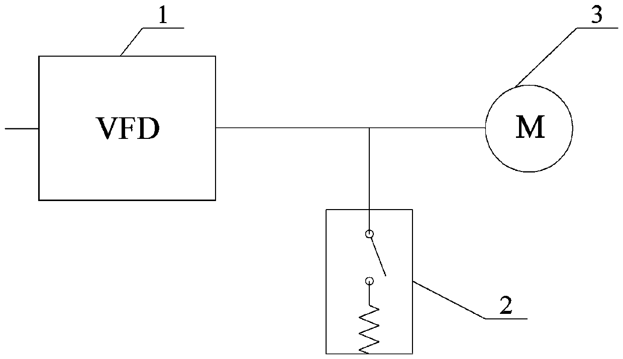
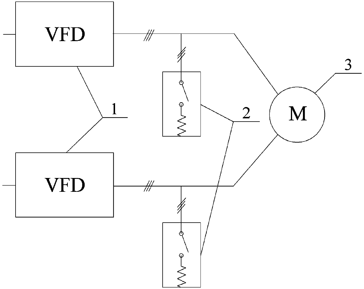
The invention discloses an integrated brake system for a converter and a working method of the integrated brake system. The integrated brake system for the converter is characterized by comprising theconverter and an AC brake unit, wherein an output end of the converter is connected with a motor; the AC brake unit is connected to the output end of the converter; in the braking process of the motor, the AC brake unit and the converter cooperatively work and generate braking torque at the same time or in a time-sharing manner; the integrated brake system for the converter comprises three working modes: an AC brake mode, an integrate brake mode and a variable-frequency brake mode in the braking process of the motor; when the integrated brake system for the converter is in the AC brake mode,the AC brake unit generates the braking torque and the converter does not generate the braking torque; when the integrated brake system for the converter is in the integrated brake mode, the AC brakeunit and the converter generate the braking torque; and when the integrated brake system for the converter is in the variable-frequency brake mode, the AC brake unit does not generate the braking torque.

Description

technical field [0001] The invention relates to a frequency converter braking system and its working method, and in particular discloses a frequency converter comprehensive braking system and its working method, which are applied in the field of motor frequency conversion drive. Background technique [0002] When using a frequency converter to drive the motor, if the motor needs to brake quickly, there are two commonly used solutions: Option 1 uses a frequency converter to achieve fast braking, such as adding chopper braking to the DC side of the frequency converter or using an active front-end rectifier ;Scheme 2 connects an AC switch and a resistor at the motor end, which is usually used for braking of a synchronous motor. When the motor brakes, close the AC switch, put the resistor in, and the motor is in the state of generating power. When it is used to excite a synchronous motor, it can also control the power absorbed by the AC resistance by controlling the motor termin...

Claims


Application Information

Patent Timeline
Patent Type & Authority Patents(China)
IPC IPC(8): H02P3/18H02P27/06H02P25/024
CPCH02P3/18H02P25/024H02P27/06
Inventor 王永红
Owner 上海德雷弗软件有限公司
Learn More