[0007]In an exemplary embodiment, according to one aspect of the invention, a NOR-gate based ring oscillator circuit for measurement of negative bias temperature instability effect includes a ring oscillator with an odd number of NOR-gates greater than or equal to three. Each of the NOR-gates has first and second input terminals, a voltage supply terminal, and an output terminal. The first input terminals of all the NOR-gates are interconnected, and each of the NOR-gates has its output terminal connected to the second input terminal of an immediately adjacent one of the NOR-gates. Also included is a voltage supply and control block. During a stress mode, this block applies a stress enable signal to the interconnected first input terminals, and an increased supply voltage to the voltage supply terminals. During a measurement mode, this block applies ground voltage to the interconnected first input terminals, and a normal supply voltage to the voltage supply terminals.
[0008]In another exemplary embodiment, according to another aspect of the invention, a NAND-gate based ring oscillator circuit for measurement of positive bias temperature instability effect includes a ring oscillator with an odd number of NAND-gates greater than or equal to three. Each of the NAND-gates has first and second input terminals, a voltage supply terminal, and an output terminal. The first input terminals of all the NAND-gates are interconnected. Each of the NAND-gates has its output terminal connected to the second input terminal of an immediately adjacent one of the NAND-gates. Also included is a voltage supply and control block. During a stress mode, this block applies a stress enable signal to the interconnected first input terminals, and an increased supply voltage to the voltage supply terminals. During a measurement mode, this block applies normal supply voltage to the interconnected first input terminals, and a normal supply voltage to the voltage supply terminals.
[0009]In yet another exemplary embodiment according to yet another aspect of the invention, a ring oscillator circuit for measurement of negative bias temperature instability effect and positive bias temperature instability effect includes a ring oscillator with first and second rails and an odd number of repeating circuit structures greater than or equal to three. Each of the repeating circuit structures includes an input terminal and an output terminal, a first p-type transistor, a first n-type transistor, and repeating-circuit-structure control circuitry. The first p-type transistor has a gate coupled to the input terminal, a first drain-source terminal coupled to the first rail, and a second drain source terminal selectively coupled to the output terminal. The first n-type transistor has a gate coupled to the input terminal, a first drain-source terminal coupled to the second rail, and a second drain source terminal selectively coupled to the output terminal. Each of the repeating circuit structures has its output terminal connected to the input terminal of an immediately adjacent one of the repeating circuit structures. Also included in the circuit is a voltage supply and control block coupled to the ring oscillator and configured to cooperate with the repeating-circuit-structure control circuitry, as follows. During a negative bias temperature instability effect direct current test mode, a stress voltage is applied to the first rail and a ground to the second rail, and the first p-type transistor of each of the repeating circuit structures is stressed. During a positive bias temperature instability effect direct current test mode, a stress voltage is applied to the first rail and a ground to the second rail and the first n-type transistor of each of the repeating circuit structures is stressed. During a measurement mode, a nominal supply voltage is applied to the first rail and a ground to the second rail, and the second drain source terminals of the first n-type transistors and the first p-type transistors are coupled to the output terminals, such that each of the repeating circuit structures functions as an inverter.
[0010]In a further exemplary embodiment according to a further aspect of the invention, a ring oscillator circuit for measurement of negative bias temperature instability effect and positive bias temperature instability effect includes a ring oscillator. The ring oscillator includes an odd number of main inverters greater than or equal to three. Each of the main inverters has an input terminal, an output terminal, a voltage supply terminal, a p-type transistor, and an n-type transistor. A plurality of first paths selectively couple the output terminals of the main inverters to the input terminals of adjacent ones of the main inverters. A plurality of inverting second paths selectively couple the output terminals of the main inverters to the input terminals of adjacent ones of the main inverters. Also included is a voltage supply and control block coupled to the ring oscillator and configured to effectuate the following. During a negative bias temperature instability effect test mode, the input of a first one of the inverters is grounded, a stress voltage is applied to the voltage supply terminals of the main inverters, the first paths are opened, and the second paths are operative to invert a signal appearing at the output terminals of the main inverters to obtain an inverted signal, and to supply the inverted signal to the input terminals of the adjacent ones of the main inverters, thus stressing the p-type transistors. During a positive bias temperature instability effect test mode, the stress voltage is applied to the voltage supply terminals of the main inverters and the input of the first one of the inverters, the first paths are opened, and the second paths are operative to invert a signal appearing at the output terminals of the main inverters to obtain an inverted signal, and to supply the inverted signal to the input terminals of the adjacent ones of the main inverters, thus stressing the n-type transistors. During a measurement mode, a nominal voltage is applied to the voltage supply terminals of the main inverters, the first paths are conductive, and the second paths are opened.
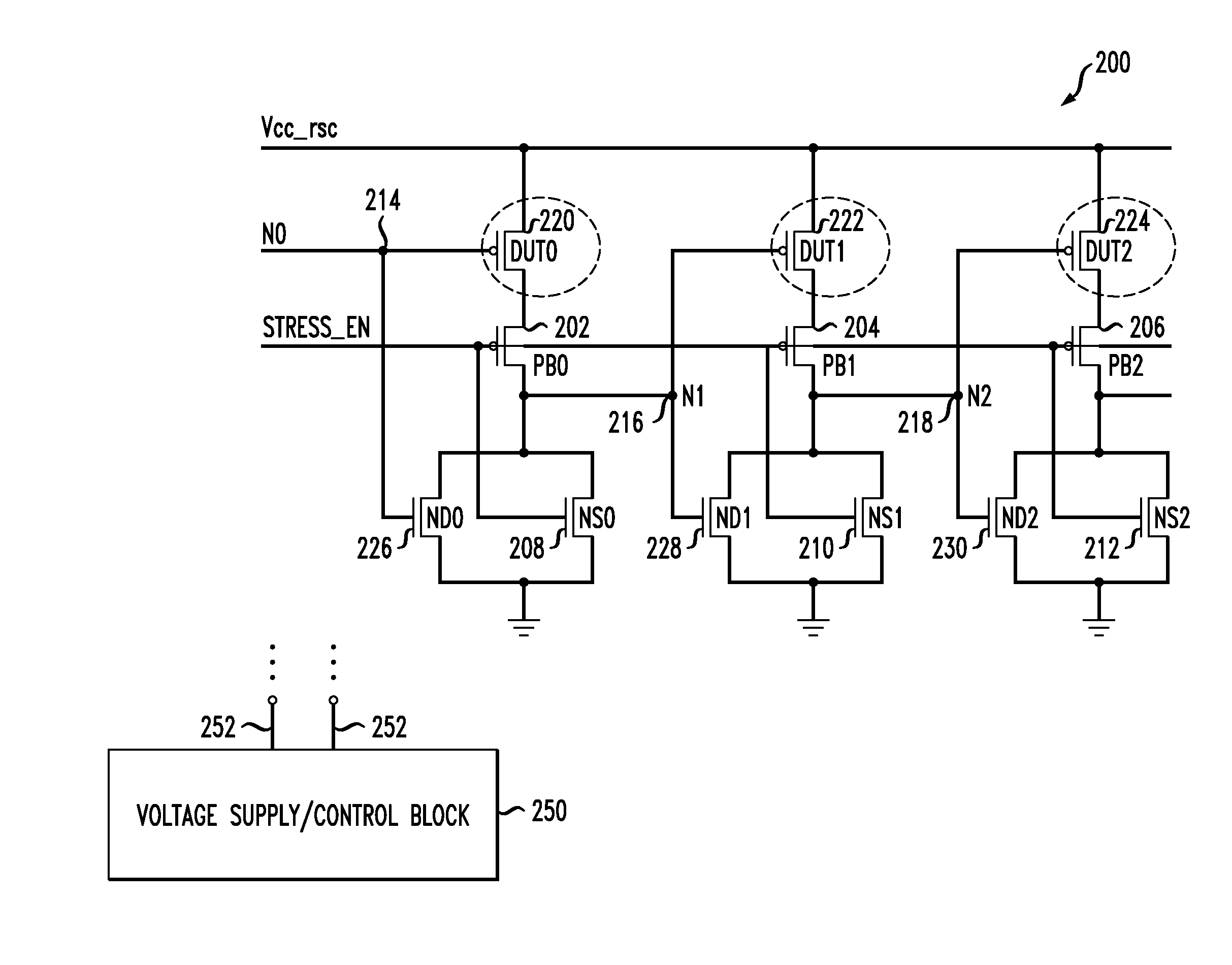
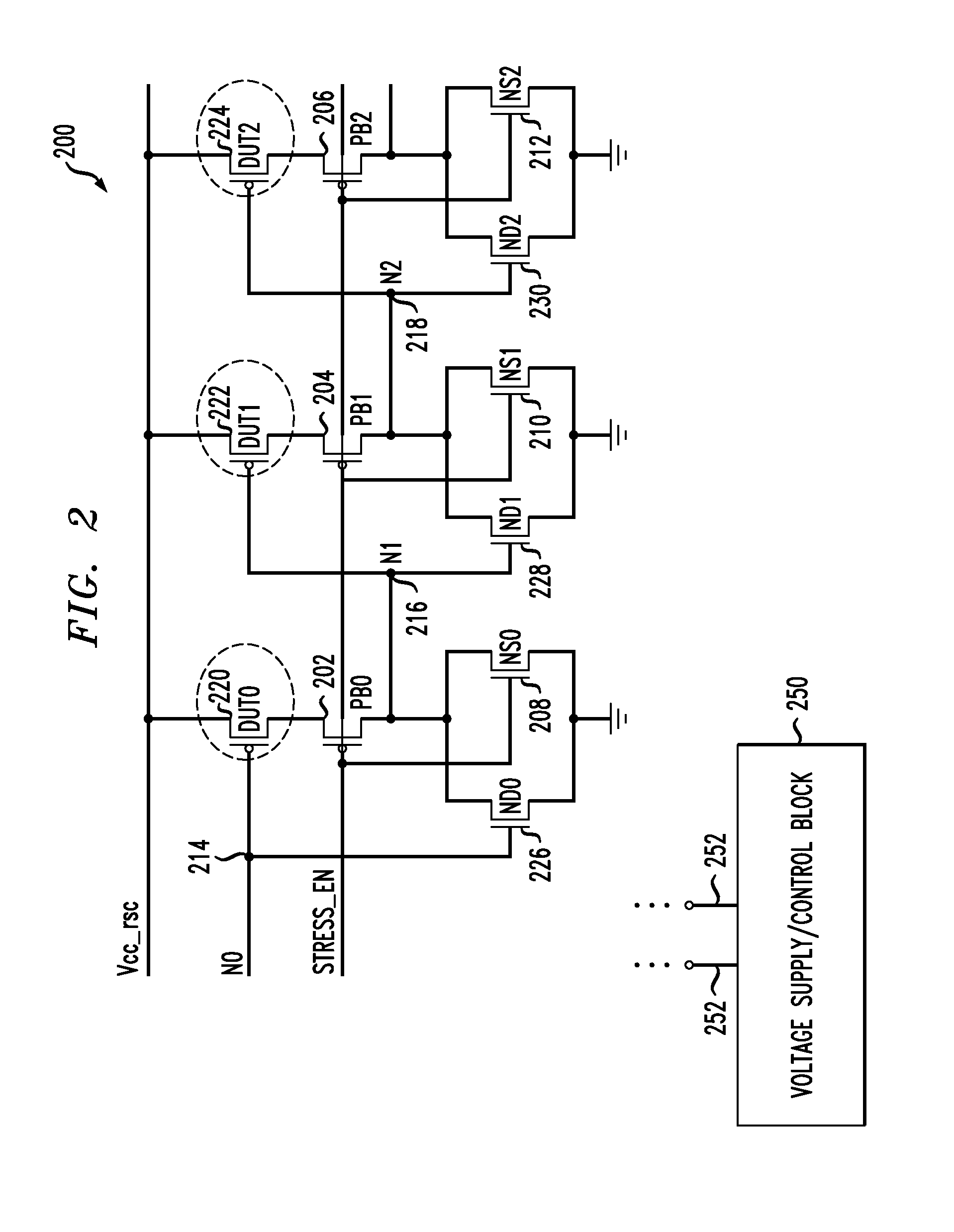
[0011]In an even further exemplary embodiment according to an even further aspect of the invention, a circuit for measuring bias temperature instability effect in pass gates includes a ring oscillator. The oscillator has an odd number of inverters greater than or equal to three. Each of the inverters has an input terminal, an output terminal, and first and second voltage supply terminals. The first voltage supply terminals of all the inverters are coupled, and the second voltage supply terminals of all the inverters are coupled. A plurality of pass transistors are configured as the pass gates, coupling the output terminals of the inverters to the input terminals of adjacent ones of the inverters. A plurality of supplemental transistors selectively couple the inputs of the inverters to (i) the second voltage supply terminals, in a case when the pass transistors are p-type, and (ii) the first voltage supply terminals, in a case when the pass transistors are n-type. A voltage supply and control block is coupled to the ring oscillator and configured such that in a stress mode, the pass transistors are stressed and the supplemental transistors are on; and in a measurement mode, the pass transistors operate with nominal voltage and the supplemental transistors are off.

