Filter device with finite transmission zeros

a filter device and transmission zero technology, applied in the field of filter devices, can solve the problem of not being able to achieve ideal bandpass filters, reduce the frequency response of filter signals, reduce the area of dual-mode filters, and increase the side length

Inactive Publication Date: 2009-07-30
NAT TAIWAN UNIV
View PDF3 Cites 17 Cited by
  • Summary
  • Abstract
  • Description
  • Claims
  • Application Information

AI Technical Summary

Benefits of technology

[0015]In summary, the filter device of the present invention is characterized by applying a metallic rectangular ring, which has a perimeter that is shorter than or equal to the wavelength corresponding to the mean of the odd mode resonant frequency and the even mode resonant frequency, thereby allowing the filter device, in the situation of specific bandpass frequency, to reduce its perimeter to about half of the perimeter of conventional annular rectangular ring filter. In addition, the locations of transmission zeros can be changed by adjusting the length/width ratio of the metallic rectangular ring. Furthermore, the frequency response of the filter signal can be reduced by disposing a gr

Problems solved by technology

In practice, no bandpass filter is ideal in that the filter does not attenuate all frequencies outside the desired frequency range completely.
Accordingly, it has become a highly urgent issue

Method used


Image

  • Filter device with finite transmission zeros
  • Filter device with finite transmission zeros
  • Filter device with finite transmission zeros

Examples


first embodiment

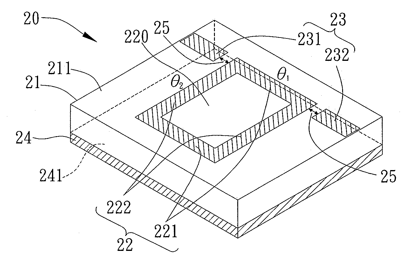
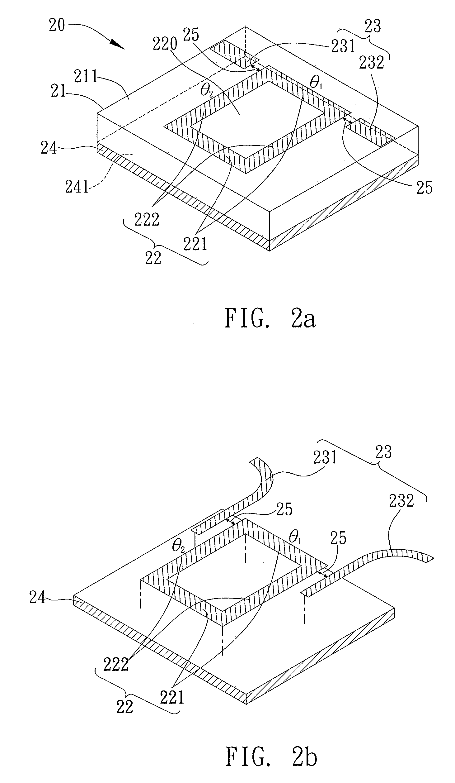
[0037]Referring to FIG. 2a, the structure of the first embodiment of the filter device of the present invention is depicted. As shown in the figure, the filter device 20 is driven by odd- and even-mode resonant frequency sources, and the filter device 20 is made up of at least: a substrate 21 including a substrate surface 211; a metallic rectangular ring 22 mounted on the substrate surface 211, wherein the perimeter of the metallic rectangular ring 22 is smaller than or equal to the wavelength corresponding to the mean of the odd mode resonant frequency and the even mode resonant frequency; a signal couple-in / couple-out module 23 including a signal couple-in portion 231 and a signal couple-out portion 232 that are mounted on the substrate surface 211; and a metallic ground plane 24 having a metallic surface 241 parallel to a plane 220 that is enclosed by the metallic rectangular ring. In particular, a microstrip line ring resonator is composed of the metallic rectangular ring 22, th...

second embodiment

[0043]Referring to FIG. 3a, the structure of the second embodiment of the filter device of the present invention is illustrated. The main difference here from that of the first embodiment is that the filter device 30 of the present embodiment further includes a ground capacitor module 31, wherein the ground capacitor module 31 has a first ground capacitor 311 and a second ground capacitor 312, and also the first ground capacitor 311 and the second ground capacitor 312 are electrically connected to middle points of the first pair of opposite sides 221, respectively.

[0044]Further referring to FIG. 3b, it illustrates changes happening to the signal frequency response of the filter device of the present invention after the first ground capacitor 311 and the second ground capacitor 312 are electrically connected to the middle points of the first pair of opposite sides 221 of the filter device respectively. In the figure, the first peak 34 corresponds to the even mode resonant frequency, ...

third embodiment

[0045]Referring to FIG. 3c, the structure of the third embodiment of the filter device of the present invention is given. The difference here from the first embodiment is that the filter device 32 in the present embodiment is further provided with a ground capacitor module 33, wherein the ground capacitor module 33 includes a third ground capacitor 331 and a fourth ground capacitor 332, allowing the third ground capacitor 331 and the fourth ground capacitor 332 to be electrically connected to the middle points of the second pair of opposite sides 222.

[0046]Further referring to FIG. 3d, it illustrates changes happening to the signal frequency response of the filter device of the present invention after the third ground capacitor 331 and the fourth ground capacitor 332 are electrically connected to the middle points of the second pair of opposite sides 222 of the filter device, respectively. It is to be noted that the third peak 36 corresponds to the even mode resonant frequency, whil...


PUM


Abstract

A filter device with transmission zeros is provided according to the present invention, which has an odd mode resonant frequency and an even mode resonant frequency. The filter device includes: a substrate, a metallic rectangular ring, a signal couple-in/couple-out module, and a metallic ground plane, wherein the surface of said metallic ground plane is parallel to the plane enclosed by said metallic rectangular ring, and said metallic rectangular ring applied to the filter device of the present invention has a perimeter shorter than or equal to the wavelength corresponding to the mean of said odd mode resonant frequency and said even mode resonant frequency, thereby allowing said filter device of the present invention, in a situation of specific bandpass frequency, to reduce its perimeter to about half of the perimeter of conventional annular rectangular dual mode filters. In addition, the locations of the transmission zeros can be changed by adjusting the length/width ratio of said metallic rectangular ring, and the frequency response of the filter signal can also be reduced by disposing a ground capacitor module. Accordingly, the area of the dual mode filter can be greatly reduced. Furthermore, the frequency response of the filter signal can be increased by disposing a ground inductor module, accordingly, decreasing the size of dual mode filter and providing a means of easy fabrication thereof.

Description

BACKGROUND OF THE INVENTION[0001]1. Field of the Invention[0002]This invention generally relates to a filter device, and more specifically, to a bandpass filter device.[0003]2. Description of Related Art[0004]A bandpass filter is a device that passes frequencies within a certain range and attenuates frequencies outside that range to an extremely low level; namely, an ideal bandpass filter would have a completely flat passband with no gain / attenuation throughout and would completely attenuate all frequencies outside the passband.[0005]In practice, no bandpass filter is ideal in that the filter does not attenuate all frequencies outside the desired frequency range completely. In particular, there is a region just on each side of the intended passband where frequencies are attenuated, but not entirely rejected.[0006]A dual mode filter is a filter design, wherein two coexisting modes of the same ring resonator or disk resonator are coupled with each other. This kind of filter has the ch...

Claims


Application Information

Patent Timeline
IPC IPC(8): H01P1/203
CPCH01P1/20381
Inventor LU, HSIN-CHIAHUANG, TIAN-WEICHANG, CHIH-CHAOCHENG, JIA-WEILEE, CHIEN-HSIEN
Owner NAT TAIWAN UNIV
Why Eureka
Try Eureka