Substrate for suspension, and production process thereof

a technology of suspension and substrate, which is applied in the direction of manufacturing tools, soldering devices, instruments, etc., can solve the problems of low productivity, increased noise of transmitted electric signals, and broken elements, and achieve the effect of preventing damage and producing at low costs

Active Publication Date: 2009-07-30
DAI NIPPON PRINTING CO LTD
View PDF1 Cites 55 Cited by
  • Summary
  • Abstract
  • Description
  • Claims
  • Application Information

AI Technical Summary

Benefits of technology

[0021]The invention produces an advantageous effect of providing a substrate for suspension which is produced at

Problems solved by technology

Accordingly, there is caused a problem that the properties of small-sized magnetic head elements are changed by electric charges collected in their sliders, and at worst the elements are broken.
Another problem is the following problem: in order to improve the signal transmission speed an

Method used


Image

  • Substrate for suspension, and production process thereof
  • Substrate for suspension, and production process thereof
  • Substrate for suspension, and production process thereof

Examples


example 1

Formation of a Substrate-Forming Member

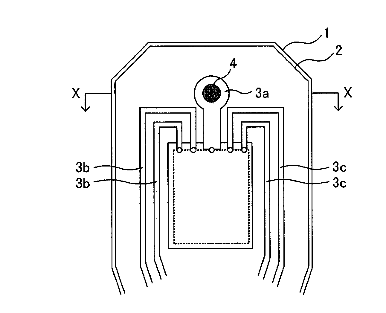
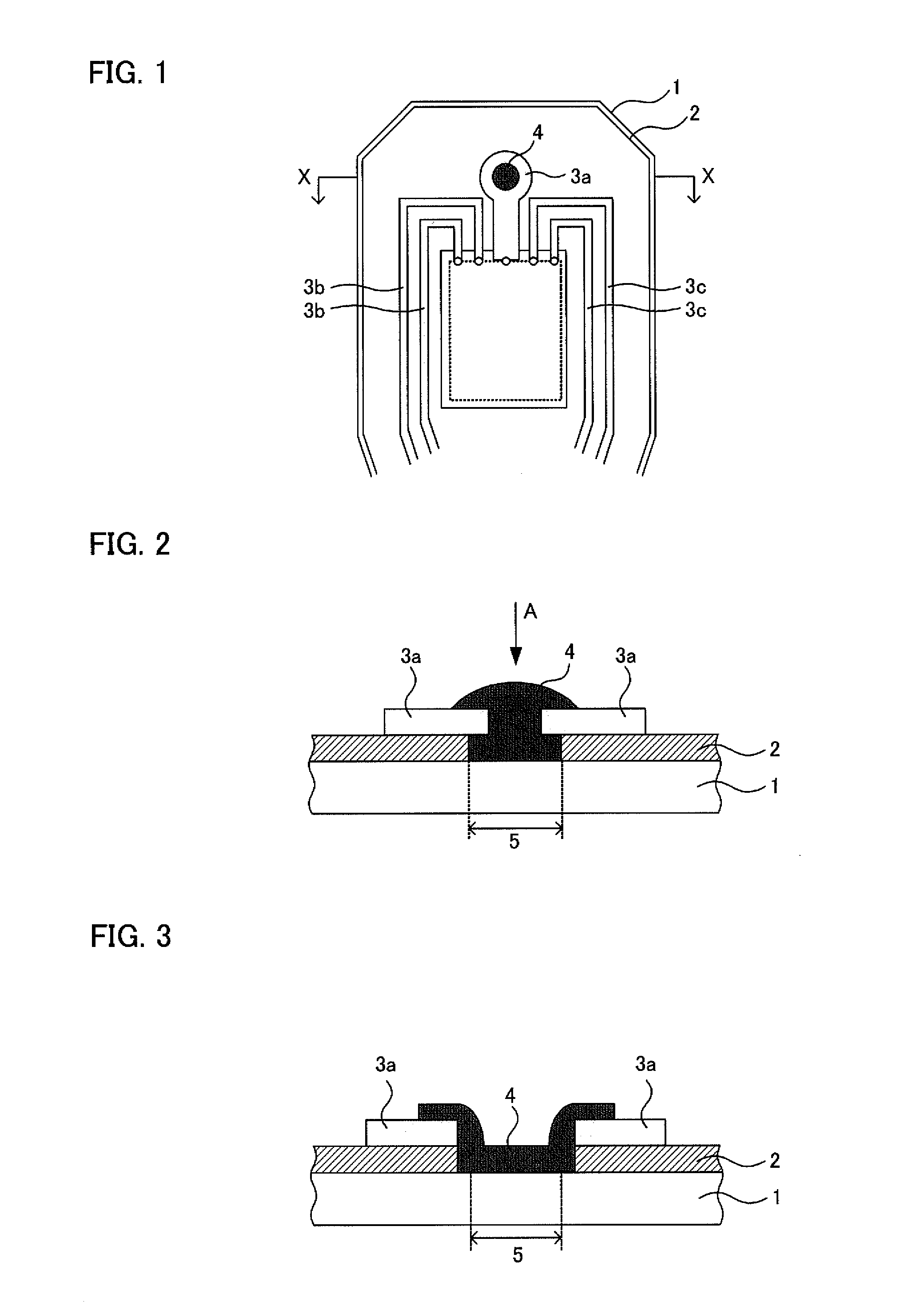
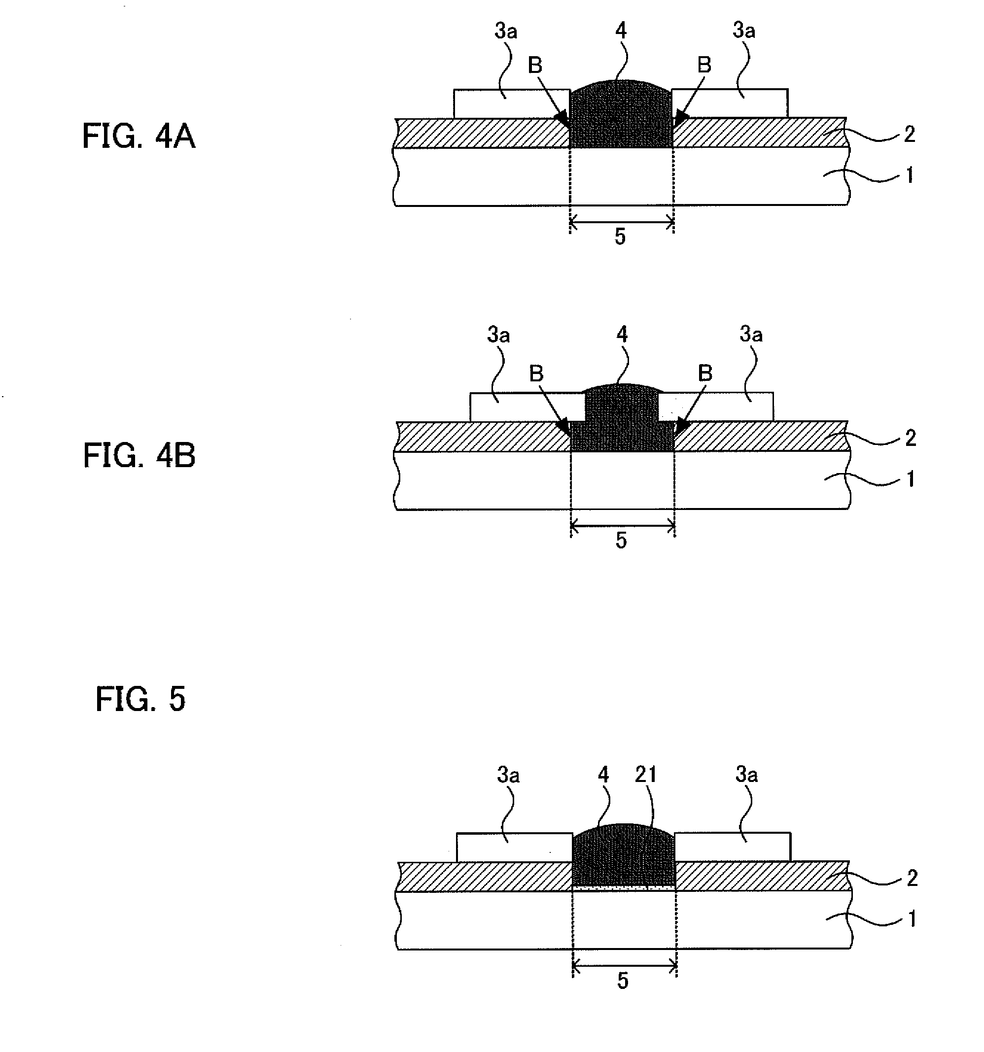
[0128]Prepared was a laminate wherein an SUS 304 of 20 μm thickness (metallic substrate), a polyimide layer of 10 μm thickness (insulating layer), and a Cu wiring layer of 18 μm thickness (wiring layer) made of electrolytic copper foil were laminated in this order. This laminate was subjected to chemical etching and other treatments described below, thereby yielding a substrate-forming member. First, a region of the Cu wiring layer where a ground terminal was to be formed (grounding Cu wiring layer) was worked into a shape having an outer diameter of 250 μm and an inner diameter (opening diameter) of 100 μm by chemical etching. Next, the SUS was chemically etched in order to specify the external shape of a substrate for suspension. Next, the polyimide layer was chemically etched to make an opening having a diameter of 100 μm. Thereafter, the surface of the grounding Cu wiring layer was plated with Ni up to a thickness of about 0.2 μm by electro...

example 2

[0130]Substrates for suspension were yielded in the same way as in Example 1 except that instead of the acid washing, a treatment with Ar gas was conducted in a parallel plate type plasma washing machine manufactured by March Plasma Systems, Inc. for 5 minutes before the melted solder was dropped, so as to activate the SUS surfaces. The average of the resistance values of the ground terminals of these substrates for suspension was 1.25Ω. The ratio of substrates having a resistance of 5Ω or less out of the substrates was 90%, and the ratio of substrates having a resistance of 1Ω or less was 65%.

example 3

[0131]Substrates for suspension were yielded in the same way as in Example 1 except that instead of the acid washing, a flux (NS-23, manufactured by Nihon Superior Co., Ltd.) for SUS was coated before the melted solder was dropped, so as to activate the SUS surfaces. The average of the resistance values of the ground terminals of these substrates for suspension was 5.55Ω. The ratio of substrates having a resistance of 5Ω or less out of the substrates was 60%, and the ratio of substrates having a resistance of 1Ω or less was 5%.


PUM

PropertyMeasurementUnit
Temperatureaaaaaaaaaa
Melting pointaaaaaaaaaa
Diameteraaaaaaaaaa

Abstract

A substrate for suspension which is produced at low costs and can sufficiently attain the prevention of damage by electrostatic discharge and restraint of noises. The substrate for suspension includes: a metallic substrate, an insulating layer formed on the metallic substrate and having an opening from which the metallic substrate is exposed, a grounding-wiring layer formed on the insulating layer and arranged near the opening, and a ground terminal formed in the opening and contacting the metallic substrate and the grounding-wiring layer. The ground terminal is made of a metal having a melting point of 450° C. or lower.

Description

TECHNICAL FIELD[0001]The present invention relates to a substrate for suspension which is produced at low costs, and can sufficiently prevent damage by electrostatic discharge and restrain noises.BACKGROUND ART[0002]In recent years, due to the spread of the Internet and others, the information processing amount of personal computers and the processing speed of information have been required to be increased. Following to that, it has been requested that the capacity of hard disc drives (HDDs) integrated into personal computers and the speed of information transmission are made larger. The type of the component for supporting a magnetic head used in an HDD, which is called a magnetic head suspension, has also been shifting from a conventional type, to which signal lines such as gold wires are connected, to a wiring-integrated type, i.e., the so-called wireless suspension type, wherein signal lines such as copper wires are fitted directly to a stainless steel spring.[0003]Recently, dem...

Claims


Application Information

Patent Timeline
IPC IPC(8): G11B5/48B23K31/02
CPCG11B5/4853
Inventor MIURA, YOICHISERIZAWA, TOORUBUSUJIMA, SHINICHIRO
Owner DAI NIPPON PRINTING CO LTD
Why Eureka
Try Eureka