
System and Methods For Speckle Reduction

a technology of speckle reduction and system and method, applied in the field of system and method for modulation of optical signals, can solve the problems of serious degradation of image quality, random granular intensity pattern known as speckle,

Inactive Publication Date: 2009-07-30
CORNING INC
View PDF31 Cites 22 Cited by
  • Summary
  • Abstract
  • Description
  • Claims
  • Application Information

AI Technical Summary

Benefits of technology

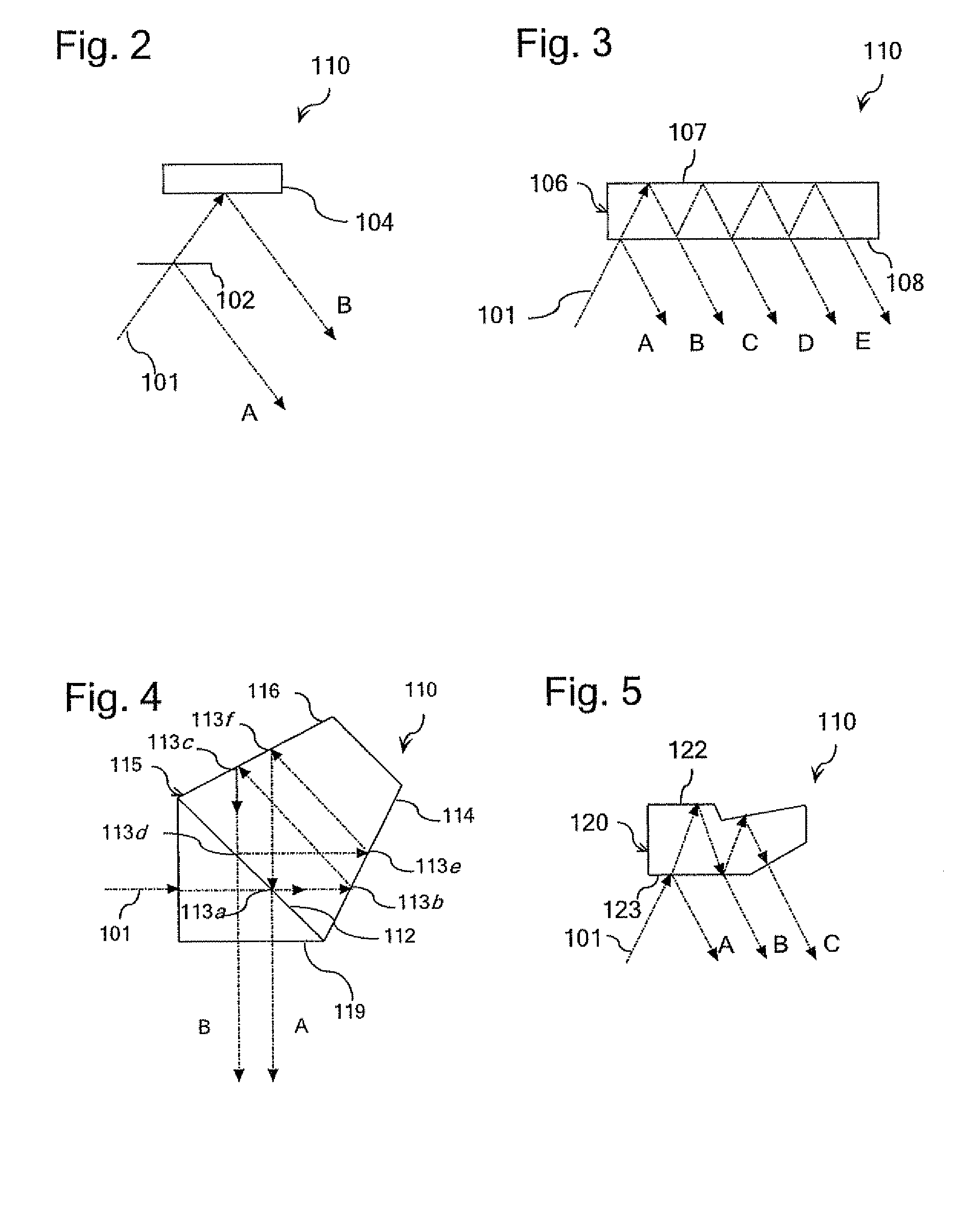
[0004]According to one embodiment of the present invention, a method of operating a laser source is provided. According to the method, a plurality of sub-beams carrying common projection data that define an optical mode are generated. Speckle contrast in an image projected using a laser source is reduced by controlling the phase of the sub-beams to continuously sequence the laser source through a plurality of orthogonal optical modes.

Problems solved by technology

Speckle may result whenever a coherent light source is used to illuminate a rough surface, for example, a screen, or any other object that produces a diffused reflection or transmission.
At an observation point, for example in the observer's eye or at the sensor of a camera, these beams interfere constructively to form a bright spot, or destructively to form a dark spot, producing a random granular intensity pattern known as speckle.
If an image is formed on the screen using laser beams, such granular structure will represent noise, or a serious degradation of the image quality.

Method used


Image

  • System and Methods For Speckle Reduction
  • System and Methods For Speckle Reduction
  • System and Methods For Speckle Reduction

Examples


Embodiment Construction

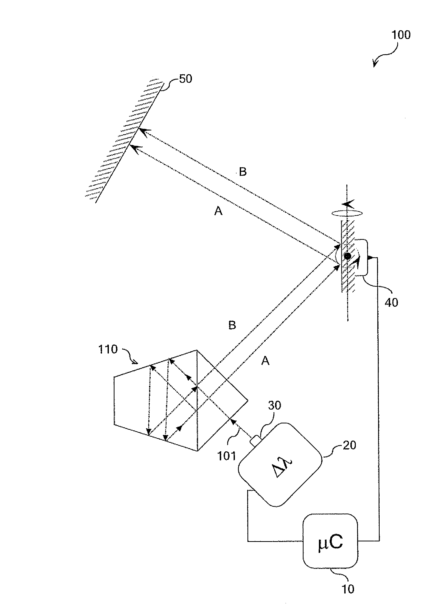
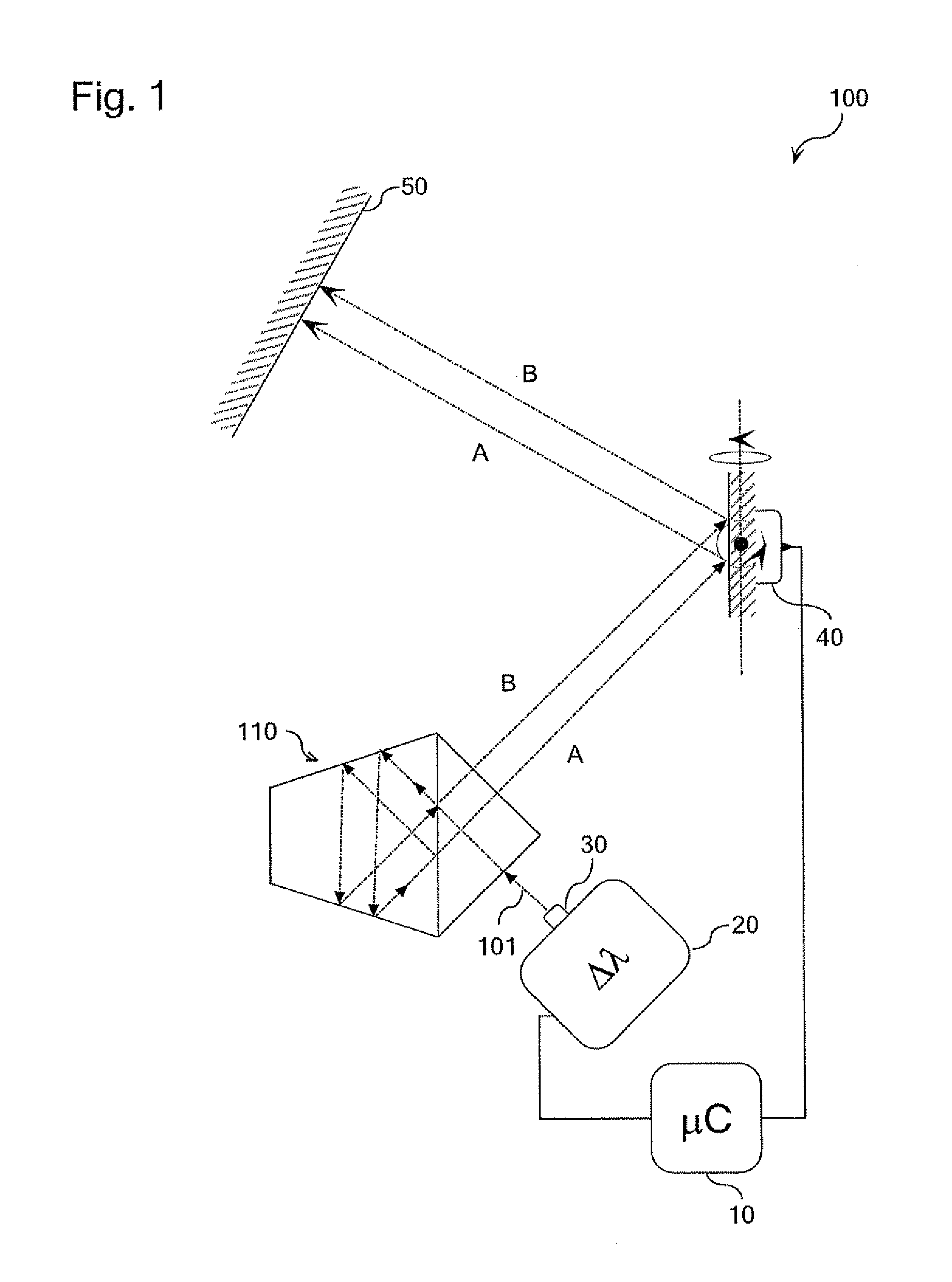
[0018]Referring initially to FIG. 1, particular embodiments of the present invention can be described in the context of a laser projection system 100 comprising a laser 30, laser driver 20, laser projection optics 40, a system controller 10 and a projected image plane 50. The laser 30 may comprise semiconductor lasers, optically pumped solid state lasers, fiber lasers, or any other type of laser capable of small wavelength modulation. FIG. 1 illustrates the particular case where a laser projection system 100 is configured to operate as a scanning projector where the laser 30 generates one or more beams by frequency conversion, e.g., green laser beams, and / or one or more optical beams natively from semiconductor lasers, e.g., red and blue laser beams.

[0019]Speckle contrast present in an image generated by a laser projection system may be reduced by sequencing an optical signal generated by a laser source through a number of orthogonal optical modes. An optical mode may be defined as ...


PUM


Abstract

A method of operating a laser source comprising is provided. The method reduces speckle contrast in a projected image by creating a plurality of statistically independent speckle patterns. The method comprises generating a plurality of sub-beams that define an optical mode. The method further comprises controlling the phase of selected sub-beams to continuously sequence the laser source through a plurality of orthogonal optical modes. The plurality of orthogonal modes create a corresponding number of statistically independent speckle patterns, thus reducing speckle contrast in a image projected using the laser source by time averaging.

Description

CROSS REFERENCE TO RELATED APPLICATIONS[0001]This application claims the benefit of U.S. Provisional Application Ser. No. 61 / 024,802, filed on Jan. 30, 2008, for Systems and Methods for Speckle Reduction. The present application is also related to copending and commonly assigned U.S. patent application Ser. No. 12 / 072,426, filed on Feb. 26, 2008, for Systems and Methods for Polarization Modulation of an Optical Signal, but does not claim priority thereto.BACKGROUND OF THE INVENTION[0002]Embodiments of the present invention relate to systems and methods for modulation of an optical signal. More specifically, embodiments of the present invention relate to the design and methods of operation of a laser source and laser projection system to reduce the presence of speckle that may be visible in a laser projection image. Speckle may result whenever a coherent light source is used to illuminate a rough surface, for example, a screen, or any other object that produces a diffused reflection ...

Claims


Application Information

Patent Timeline
Patent Type & Authority Applications(United States)
IPC IPC(8): H01S3/00
CPCH04N9/3129G02B27/48
Inventor KUKSENKOV, DMITRI VLADISLAVOVICHHEMPSTEAD, MARTIN
Owner CORNING INC
Learn More