Motor controller and vehicular steering system using said motor controller

a motor controller and steering system technology, applied in the field of motor controllers, can solve the problems of reducing the accuracy of the estimated rotor, reducing the accuracy of the rotor rotation speed, and affecting the accuracy of the estimated rotor, so as to improve the steering feel, reduce the transmission of unstable torque to the steering mechanism, and improve the effect of accuracy

Inactive Publication Date: 2009-07-30
JTEKT CORP
View PDF3 Cites 24 Cited by
  • Summary
  • Abstract
  • Description
  • Claims
  • Application Information

AI Technical Summary

Benefits of technology

[0013]Therefore, this invention provides a motor controller which can appropriately use low speed region position estimation and high speed region position estimation depending on the rotor rotation speed, and as a result, accurately calculate the rotor position and thus improve the accuracy with which the motor is controlled.
[0032]In the vehicular steering system as described above, the current command value generating portion may reduce the current command value as the rotation speed decreases when the speed of the vehicle detected by the vehicle speed sensor is not zero, and the detected rotation speed is in the medium speed region. When the rotation speed of the rotor or the like is in the medium speed region, the accuracy with which the high speed region position estimating portion estimates the rotational position of the rotor decreases as the rotor rotation speed decreases. Therefore, when the vehicle is moving and the rotation speed of the rotor or the like is in the medium speed region, the current command value is reduced as the rotation speed decreases. As a result, an odd steering feel caused by unstable torque being generated by the motor can be reduced.

Problems solved by technology

However, with a structure in which the rotor rotation speed is obtained based on the estimated rotor position, impulse noise and the like adversely affects the accuracy of the estimated rotor position, which in turn reduces the accuracy of the rotor rotation speed.
Therefore, there may be erroneous switching between the low speed region position estimating process and the high speed region position estimating process, which may cause a temporary decrease in the position estimating accuracy.

Method used


Image

  • Motor controller and vehicular steering system using said motor controller
  • Motor controller and vehicular steering system using said motor controller
  • Motor controller and vehicular steering system using said motor controller

Examples


Embodiment Construction

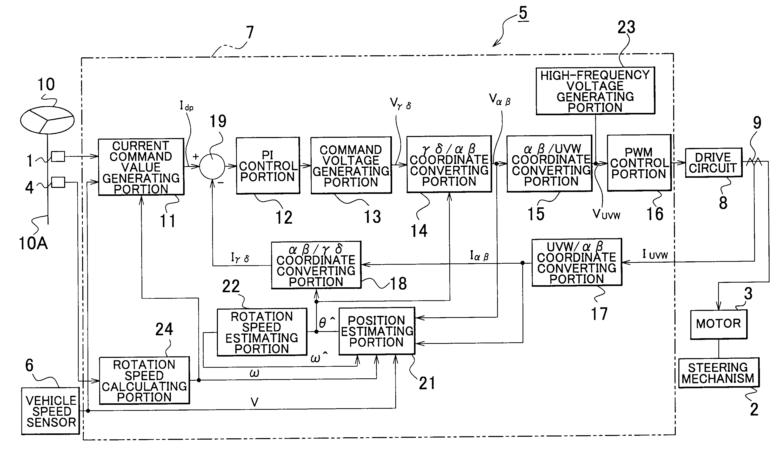
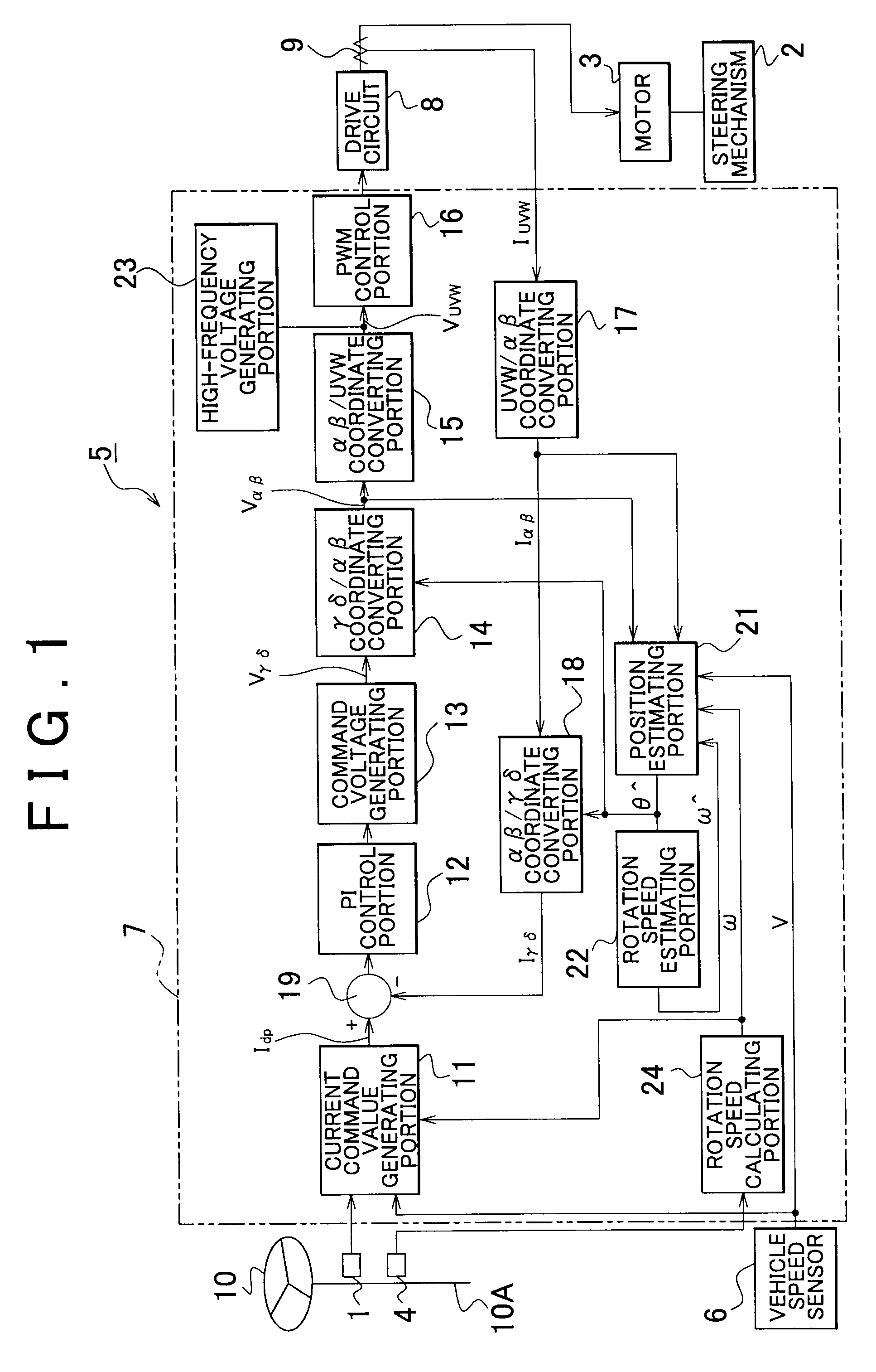
[0045]Example embodiments of the present invention will be described in greater detail below with reference to the accompanying drawings. FIG. 1 is a block diagram of the electrical configuration of an electric power steering system (i.e., one example of a vehicular steering system) to which a motor controller according to one example embodiment of the invention has been applied. This electric power steering system includes a torque sensor 1 that detects steering torque applied to a steering wheel 10 which serves as a steering member for steering a vehicle, a motor 3 (i.e., an electric motor) that applies steering assist force to a steering mechanism 2 of the vehicle, a steering sensor 4 that detects the steering angle which is the rotation angle of the steering wheel 10, a motor controller 5 that controls (i.e., drives) the motor 3, and a vehicle speed sensor 6 that detects the speed of the vehicle provided with the electric power steering system.

[0046]The motor controller 5 provid...


PUM


Abstract

A low speed region position estimating portion is designed to be suitable for when the motor is operating in a low speed region, and estimates a low speed estimated rotational position θ̂L. A high speed region position estimating portion is designed to be suitable for when the motor is operating in a high speed region, and estimates a high speed estimated rotational position θ̂H. A dividing portion obtains a divided estimated rotational position θ̂M by internally dividing the low speed estimated rotational position θ̂L and the high speed estimated rotational position θ̂H. A rotation speed calculating portion obtains a rotation speed ω of a rotor based on an output signal from a steering sensor. The rotational position of the rotor is then obtained by selecting one of i) the low speed estimated rotational position θ̂L, the high speed estimated rotational position θ̂H, or the divided estimated rotational position θ̂M, based on that rotation speed ω.

Description

INCORPORATION BY REFERENCE[0001]The disclosure of Japanese Patent Application No. 2008-019535 filed on Jan. 30, 2008, including the specification, drawings and abstract is incorporated herein by reference in its entirety.BACKGROUND OF THE INVENTION[0002]1. Field of the Invention[0003]The invention relates to a motor controller for driving a brushless motor without using sensors, as well as to a vehicular steering system which uses that motor controller. A brushless motor is used as a source for generating steering force or steering assist force in an electric power steering system or other vehicular steering system, for example.[0004]2. Description of the Related Art[0005]A motor controller for controlling (i.e., driving) a brushless DC motor typically configured to control the supply of motor current according to output from a position sensor that detects the rotational position of a rotor. However, in addition to the position sensor not being very environmentally resistant, expens...

Claims


Application Information

Patent Timeline
Patent Type & Authority Applications(United States)
IPC IPC(8): H02P7/06H02P6/16H02P6/18B62D5/04H02P6/06H02P6/08H02P6/182H02P21/00H02P21/04H02P21/14H02P21/18H02P21/24H02P21/28H02P21/32H02P23/03H02P23/12H02P23/14H02P27/04
CPCH02P21/04B62D5/046H02P21/18H02P21/34
Inventor KOMATSU, HAYATOTANIZAWA, AKIRASEGAWA, MASAYAKARIATSUMARI, YUJI
Owner JTEKT CORP
Why Eureka
Try Eureka