Multi-Axis Wind Turbine With Power Concentrator Sail

a multi-axis, wind turbine technology, applied in the direction of electric generator control, renewable energy generation, greenhouse gas reduction, etc., can solve the problems of obscuring the landscape, needing an even horizontal air inflow, danger to birds and air traffic, etc., to prevent the disruption of rotation, reliable and effective

Inactive Publication Date: 2009-07-30
KNUTSON ROGER C
View PDF45 Cites 53 Cited by
  • Summary
  • Abstract
  • Description
  • Claims
  • Application Information

AI Technical Summary

Benefits of technology

[0015]The present wind turbine is able to operate in very broad wind conditions, such as velocities up to 100 mph, and frequently changing wind directions. The sail of the present wind turbine provides a reliable and effective means for directing air currents into the rotor assembly, which can be attached directly to a vertical shaft or serve as a rotor to an integrated alternator.
[0016]The invention involves various embodiments of a vertical-axis wind turbine. Pr

Problems solved by technology

Horizontal axis windmills have been used extensively to drive electrical generators, however they suffer from several disadvantages, including the need for an even horizontal air inflow, danger to birds and air traffic, obscuring the landscape with banks of rotating windmills, and in the case of large diameter horizontal axis propellers, supersonic speeds at the tips of the rotors.
This disadvantageously adds additional moving parts to the wind gathering and electrical energy producing parts.
A major drawback of this design is the fact that the air intake module needs to face the wind, so it requires a yaw mechanism to orient it into the wind.
The numerous and drastic changes in airflow directions entail a power loss in the airflow and a re

Method used


Image

  • Multi-Axis Wind Turbine With Power Concentrator Sail
  • Multi-Axis Wind Turbine With Power Concentrator Sail
  • Multi-Axis Wind Turbine With Power Concentrator Sail

Examples


Embodiment Construction

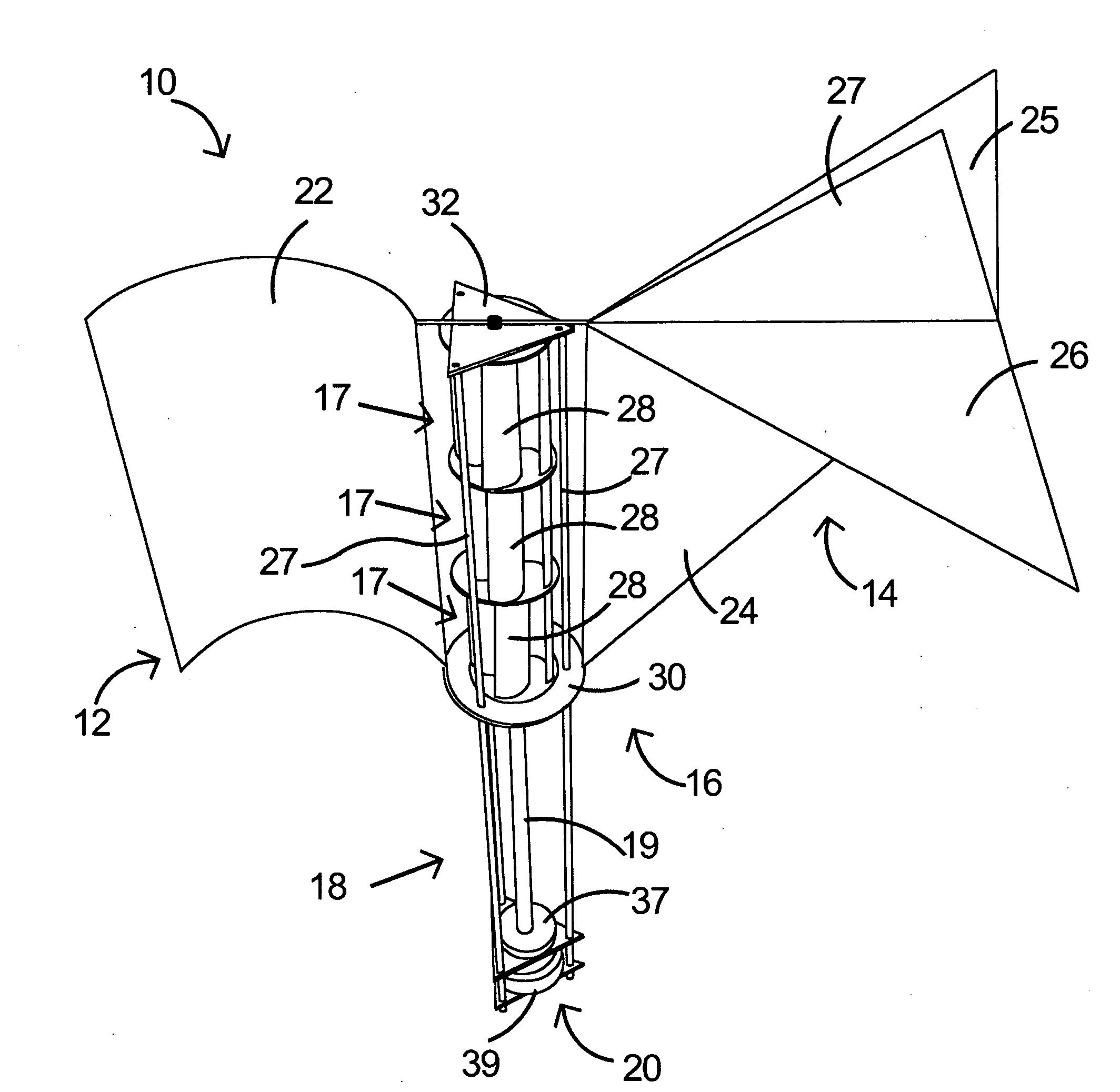
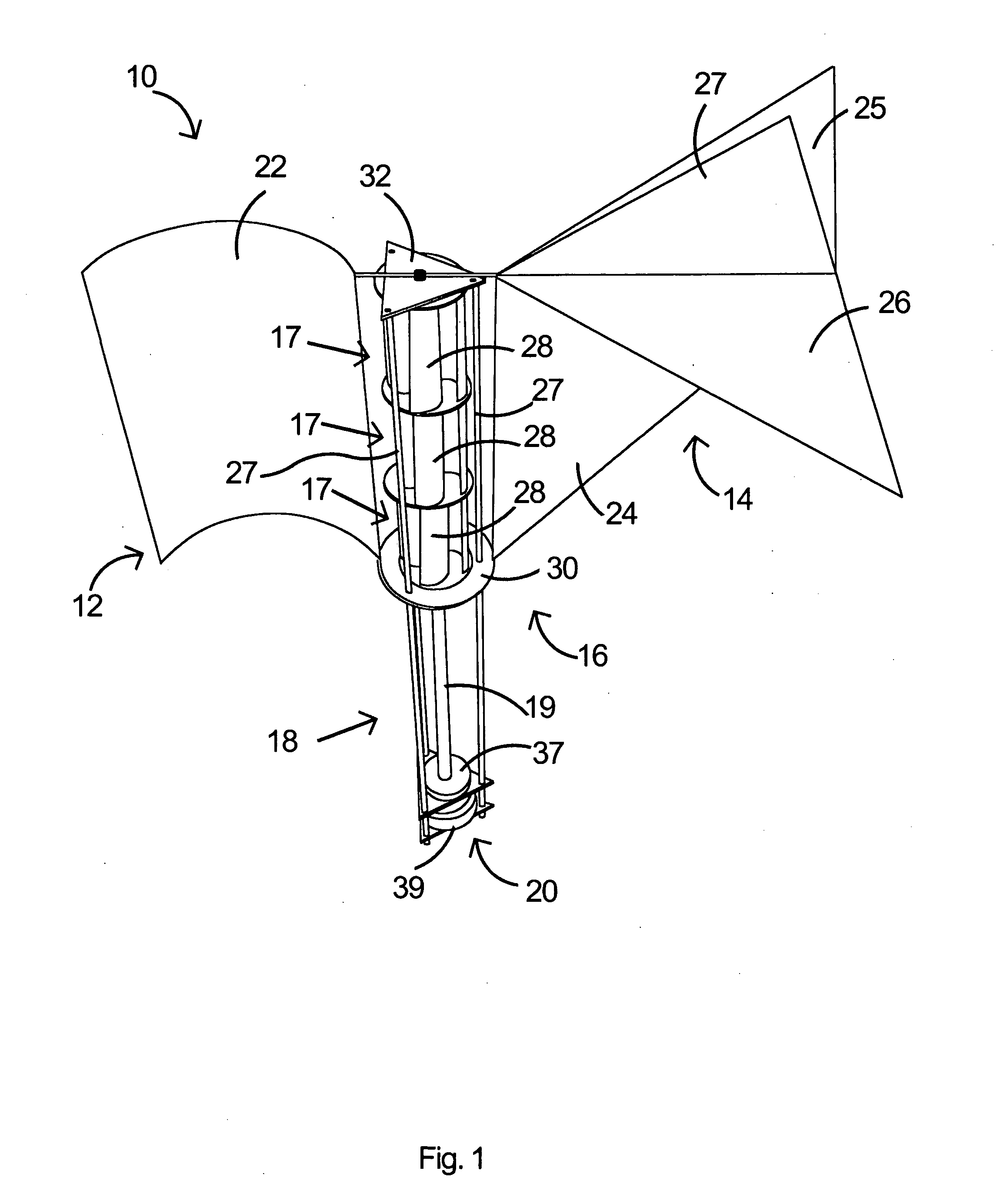
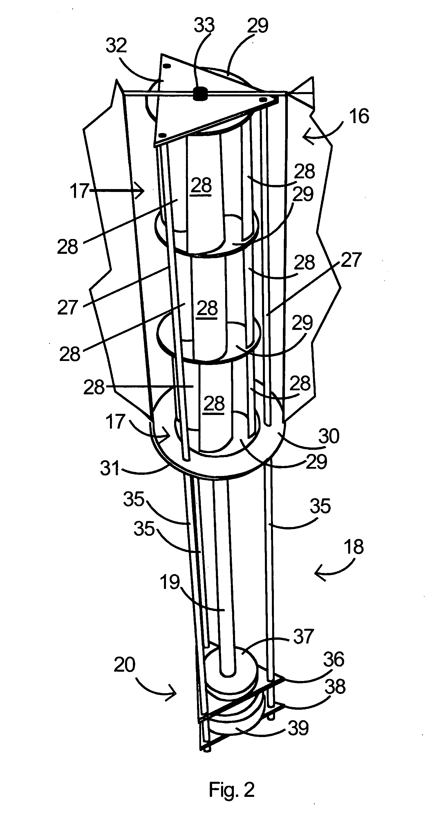
[0035]FIGS. 1 and 11 show a vertical axis wind turbine (VAWT) 10 as seen from the exterior thereof, having a front sail 12, a trailing or tail sail 14, a turbine assembly 16 (e.g. Savonius turbines), and electricity generator section 20, all on a base or stand 18. The turbine assembly 16 is shown having a plurality (3) of wind vane assemblies 17. It should be appreciated, however, that the turbine assembly 16 may have only one vane assembly 17, two or more that three vane assemblies 17 as desired. The incident wind is captured and directed into the rotor vanes 28 of each vane assembly 17 via the front sail 12. The position of the front sail 12 with respect to the wind is maintained by the tail sail 14. The front sail 12 is characterized by a curved panel 22 that directs the wind into the vane assemblies 17. The tail sail 14, as best seen in FIG. 7, includes a front panel 24, left and right cross panels 26, 25 and vertical panel 27. This configuration is similar to the tail of an air...


PUM


Abstract

A wind energy to electrical power conversion device provides a protected multiple turbine mechanism axially aligned to convert kinetic energy of air movement, i.e. wind (or other moving fluid such as water), into rotational mechanical power to directly create electrical energy by the reaction of the wind with the turbine. The present wind energy to electrical power conversion device may either be configured as a vertical axis wind turbine (VAWT) or horizontal axis wind turbine (HAWT). An associated wind gathering sail automatically repositions itself to maximize wind intake and to collect and concentrate the wind prior to converting the wind into energy via the axially aligned multi-turbine mechanism into electrical energy. The remaining wind is released via a leeward-facing exhaust. The present axially aligned multi-turbine mechanism avoids interference by birds and other outside objects due to its inherent structural visibility.

Description

RELATED APPLICATIONS[0001]This patent application claims the benefit of and / or priority to U.S. Provisional Patent Application Ser. No. 61 / 062,247 filed Jan. 24, 2008, entitled “Power Concentrator Sail and Multi-Axis Wind Turbine” the entire contents of which is specifically incorporated herein by this reference.BACKGROUND OF THE INVENTION[0002]1. Field of the Invention[0003]The present invention relates to wind turbines utilized to convert wind energy into electro-mechanical energy and, more specifically, to vertical axis wind turbines for directly producing electrical energy.[0004]2. Background Information[0005]Wind as a source of energy is a development that has existed from distant historical accounts. There is evidence which indicates windmills were in use in Babylon and in China as early as 2000 B.C.[0006]Wind is presently used as a source of energy for driving horizontal axis and vertical axis windmills. Horizontal axis windmills have been used extensively to drive electrical...

Claims


Application Information

Patent Timeline
IPC IPC(8): F03D3/04F03D9/00
CPCF03D3/0481F03D9/002Y02E10/74F05B2240/40F05B2250/25F05B2240/213F03D9/25F03D3/0454F03D3/02F03D80/70F03D15/10F03D17/00F03D9/11
Inventor KNUTSON, ROGER C.
Owner KNUTSON ROGER C
Why Eureka
Try Eureka