

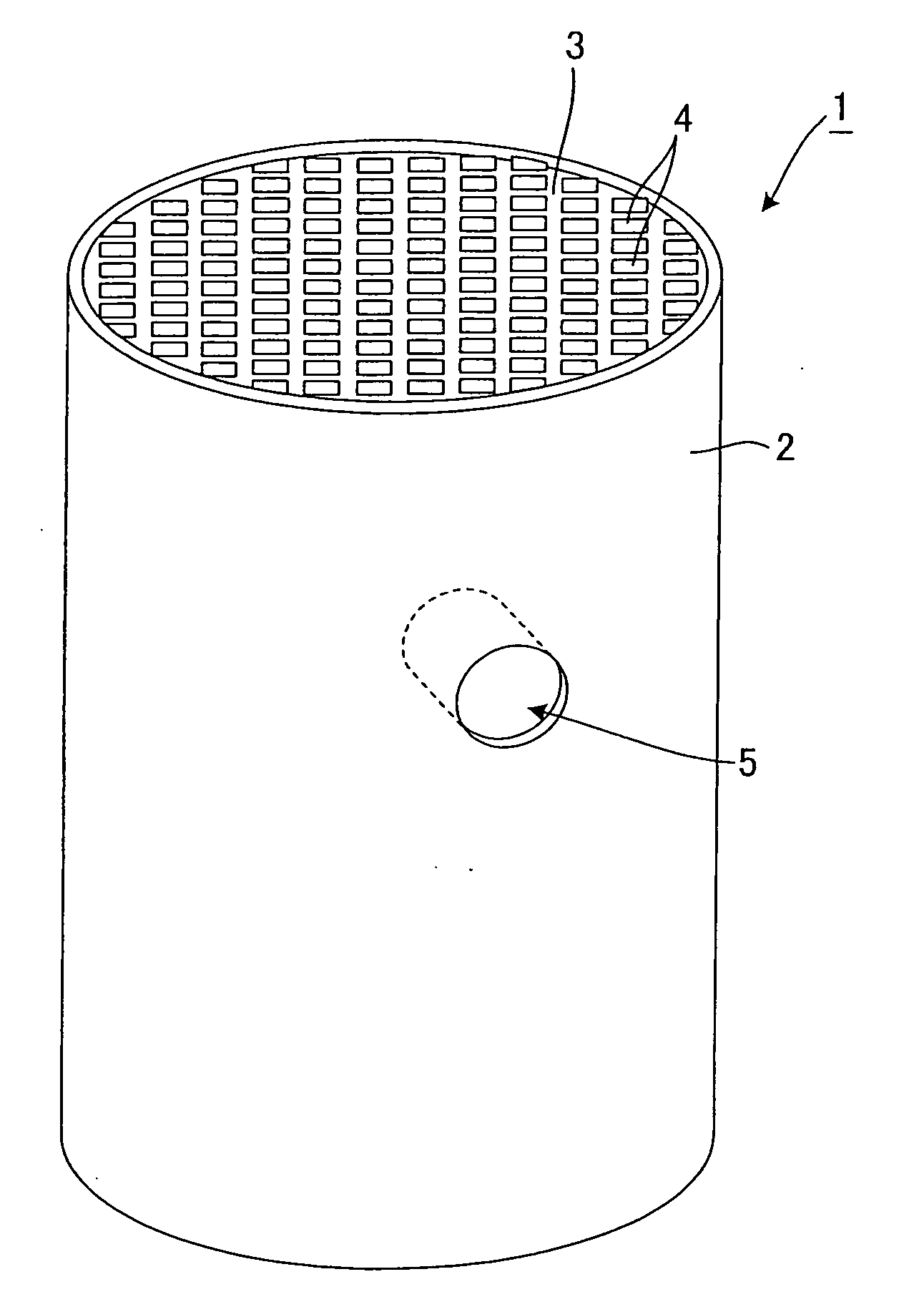
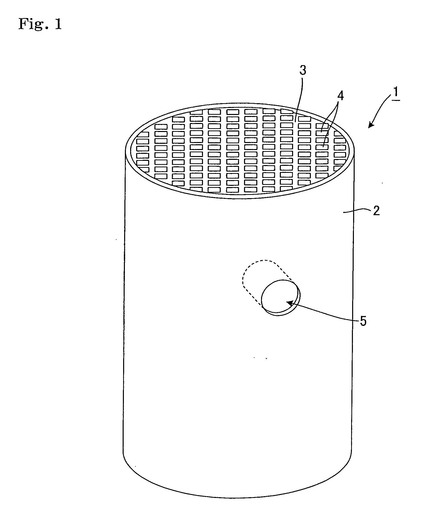
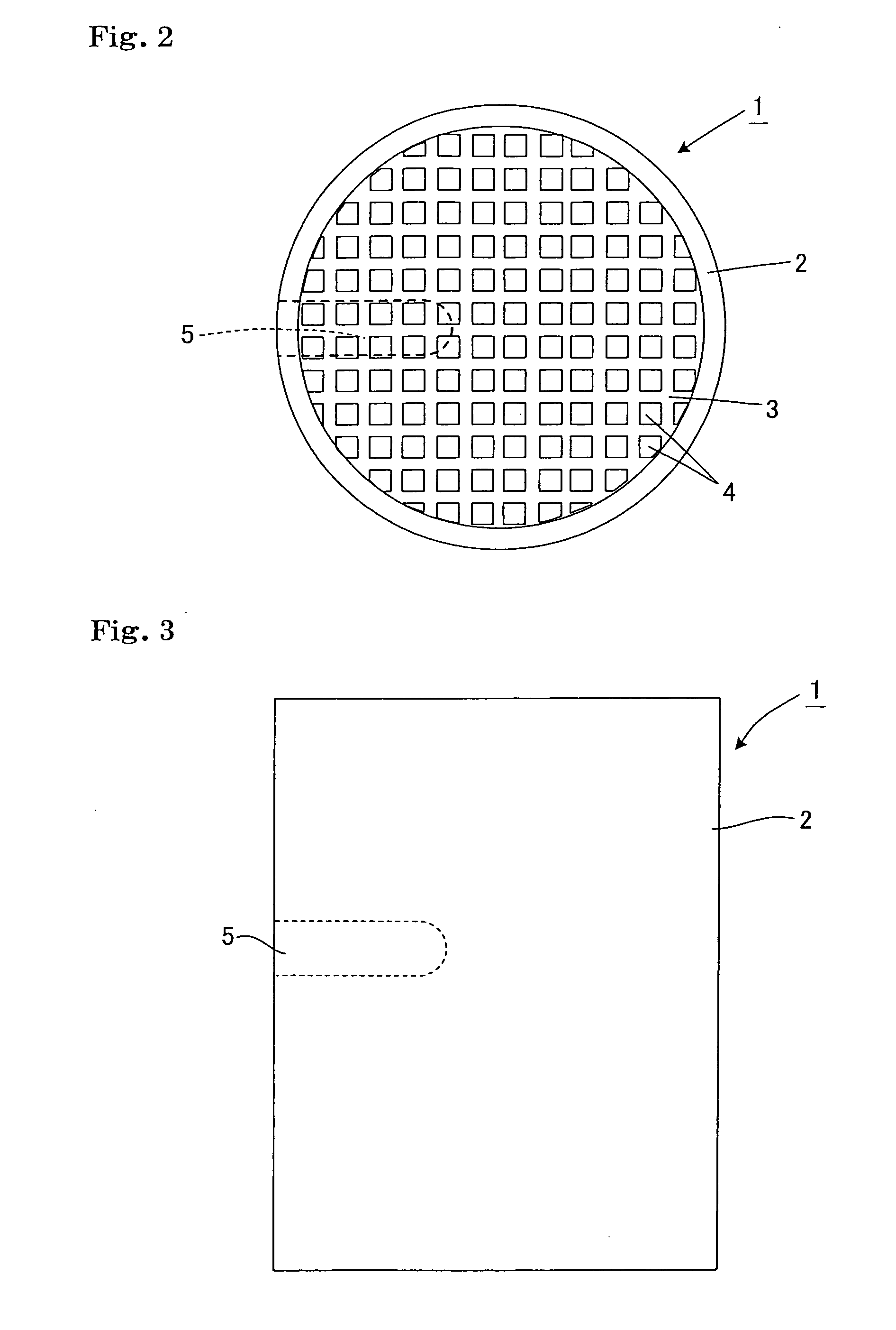
Method of producing perforated honyecomb structure body
a technology of honeycomb and structure body, which is applied in the field of can solve the problems of affecting the quality of honeycomb, the sharpness of the grinding tool rapidly deteriorates during grinding, and the shape of the hole may be distorted, so as to achieve the effect of effectively preventing chipping, facilitating and inexpensively producing a perforated honeycomb structure body
- Summary
- Abstract
- Description
- Claims
- Application Information
AI Technical Summary
Benefits of technology
Problems solved by technology
Method used
Image

Examples
example 1
[0120]As a grinding tool shown in FIGS. 5A and 5B, a hole having a depth of 20 mm was formed in each of two hundred honeycomb structure bodies having the above-described configuration using a wheel grinder 14 in which abrasive grains 12 were disposed on the outer circumferential surface and the end face of a cylindrical metal shaft 11 and grooves 13 were formed in the surface of the wheel grinder 14 along the grinding direction to obtain perforated honeycomb structure bodies.
[0121]In the wheel grinder, diamond abrasive grains having a particle diameter of 100 to 150 μm were disposed to a thickness of 3 mm. The width of the grooves formed in the wheel grinder was 1.5 mm. Four grooves were formed in the wheel grinder so that the grooves were connected at the center of the tip of the wheel grinder. The outer diameter (maximum outer diameter) of the area of the wheel grinder in which the abrasive grains were disposed was 18 mm. The ratio of the total area of the grooves formed in the wh...
examples 2 to 8
[0123]Two hundred perforated honeycomb structure bodies were produced in the same manner as in Example 1 using a wheel grinder similar to that of Example 1, except that the rotational speed, the feed speed, the feed amount per rotation, and the groove ratio were changed as shown in Table 1.
examples 9 to 15
[0124]Two hundred perforated honeycomb structure bodies were produced in the same manner as in Example 1, except that the groove width of the wheel grinder was changed as shown in Table 2, and the rotational speed, the feed speed, the feed amount per rotation, and the groove ratio were changed as shown in Table 2 in order to check the effect of the groove width.
TABLE 2Example 9Example 10Example 11Example 12Example 13Example 14Example 15Grinding toolWheel grinder(four grooves,(four grooves,(four grooves,(two grooves,(twelve grooves,(four grooves,(four grooves,groove width:groove width:groove width:groove width:groove width:groove width:groove width:4 mm)0.5 mm)1 mm)0.5 mm)0.5 mm)5 mm)1.5 mm)Grinding tool rotational3000300030001000300030001000speed (rpm)Grinding tool feed rate30030030050300300200(mm / min)Grinding tool feed methodOne stepOne stepOne stepOne stepOne stepOne stepOne stepFeed amount per rotation0.10.10.10.050.10.10.2(mm)Groove ratio (%)28.33.57.11.810.635.410.6ChippingGood...
PUM
| Property | Measurement | Unit |
|---|---|---|
| width | aaaaa | aaaaa |
| angle | aaaaa | aaaaa |
| thickness | aaaaa | aaaaa |
Abstract
Description
Claims
Application Information