
Core suction technique for the fabrication of optical fiber preforms

a technology of optical fiber and preforms, which is applied in the field of preforms for the fabrication of optical fibers, can solve the problems of high toxicity, very slow and somewhat complicated process, and none of the above known techniques of fabricating optical fiber preforms lend themselves particularly well to confinement of substances and vapors

Inactive Publication Date: 2009-08-06
VIRGINIA TECH INTPROP INC +1
View PDF4 Cites 2 Cited by
  • Summary
  • Abstract
  • Description
  • Claims
  • Application Information

AI Technical Summary

Benefits of technology

[0011]It is another object of the present invention to provide an alternative, rapid, repeatable, robust and economical technique of producing optical fiber preforms to known techniques of fabricating optical fiber preforms, particularly for HNLFs.
[0012]It is a further object of the invention to provide an arrangement for fabrication of fiber optic preforms which allows safe fabrication even if toxic substances are to be included in the glass core.
[0013]It is yet another object of the invention to provide a technique of forming preforms, particularly preforms with very small diameter cores, and which will decrease the incidence of breakage and defects.

Problems solved by technology

MCVD techniques which involve a layer-by-layer deposition of material of a core (which can form a highly non-linear optical region) inside a cladding tube, offer the greatest potential for high purity and tight confinement but the processes are very slow and somewhat complicated, particularly for multi-component glasses in the core.
Also, since HNLFs and highly doped glasses are non-standard, it may be desirable to include any of a wide variety of materials in the core glass, some of which may be highly toxic.
None of the above known techniques of fabricating optical fiber preforms lend themselves particularly well to confinement of substances and vapors which may be toxic without the addition of particular structures for that purpose or other significant complication of the respective processes.
The most significant difficulty with these techniques derives from the desired small core diameter of the final fiber drawn from the preform.
Thus, the core glass fiber would have to be drawn to a diameter of less than 40 microns prior to being inserted into a cladding tube (of a type which allows splicing to other fibers) before the assembly is drawn to final desired dimensions thus complicating and introducing additional failure modes into the assembly and drawing processes to produce the preform and then the optical fiber.
Further, additional problems have been encountered in known assembly and fabrication techniques for HNLFs.
For example, trapped air entrained due to the necessary initial clearance between cladding and core may form bubbles within the cladding and it is anticipated that such bubbles will become more of a problem as the core and cladding bore become smaller.
There is also a limit to the size from which a fiber having the desired final dimensions can be drawn due to the large thermal expansion coefficient (CTE) of high non-linearity glasses.
These assembly and drawing techniques can also be sources and opportunities for contamination of the fiber at several stages of these processes.

Method used


Image

  • Core suction technique for the fabrication of optical fiber preforms
  • Core suction technique for the fabrication of optical fiber preforms

Examples


Embodiment Construction

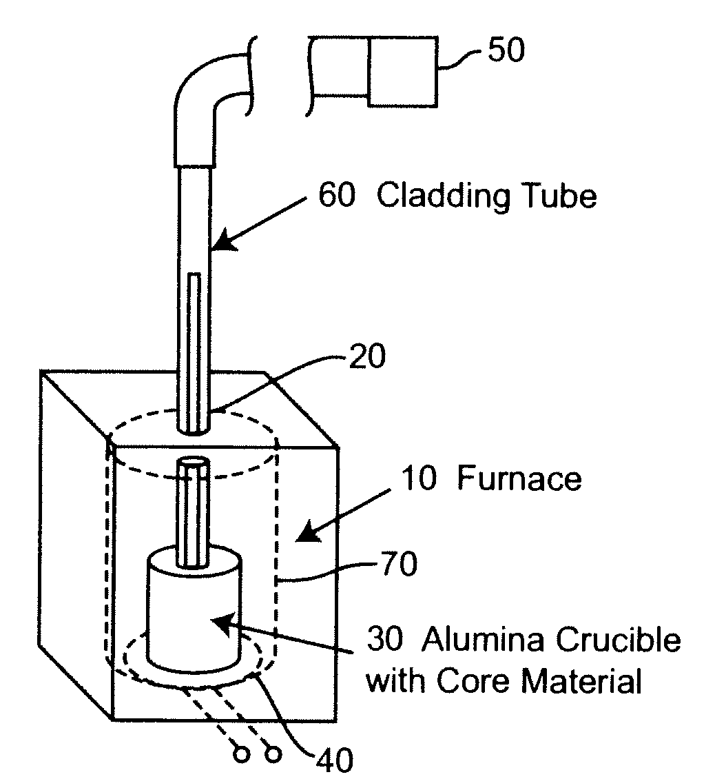
[0020]Referring now to the drawings, and more particularly to FIG. 1, there is shown a schematic depiction of basic apparatus for practice of the invention by which the principles and methodology of the invention sufficient to its successful practice may be readily conveyed to those skilled in the art. The basic apparatus sufficient to practice the invention is extremely simple and suitable structures from which the apparatus may be assembled are commercially available. Basically, the apparatus comprises a muffle furnace 10 or other type of furnace preferably dimensioned to accommodate a principal portion, if not all, of a preform of the desired length which is generally equipped with a thermometer hole 20. (In general, the preform that can be fabricated will be substantially limited to the portion of the cladding tube which can be heated in the furnace since the core glass will generally solidify quickly upon reaching an unheated portion of the cladding tube. Common sizes of thermo...


PUM

PropertyMeasurementUnit
core diameteraaaaaaaaaa
inner diameteraaaaaaaaaa

Abstract

Optical fiber preforms which can be drawn into optical fibers of desired dimensions are fabricated by applying a vacuum to a cladding tube and drawing molten glass from a crucible into a bore of the cladding tube while a portion of the cladding tube is within a furnace preferably through a small hole in the top of the furnace. The method and apparatus are particularly applicable to highly non-linear fiber (HNLF) glasses and highly doped or rare earth glasses since materials therein are generally expensive and only a small quantity of molten glass is required but can be applied to virtually any optical fiber construction where the core glass has a lower melting or softening point than that of the cladding tube. Sources of contamination, breakage and other preform defects are substantially avoided and toxic substances, if present are readily confined.

Description

CROSS-REFERENCE TO RELATED APPLICATIONS[0001]This application claims benefit of priority of U.S. Provisional Patent Application Ser. No. 60 / 680,045, filed May 12, 2005, which is hereby incorporated by reference in its entirety.STATEMENT OF GOVERNMENT INTEREST[0002]The development of this invention was funded by the National Science Foundation, grant number ECS-0123484 and the National Institute of Aerospace, grant number VT-03-1. Accordingly, the United States Government has certain interests in this invention.BACKGROUND OF THE INVENTION[0003]1. Field of the Invention[0004]The present invention generally relates to optical fibers and, more particularly, to preforms for the fabrication of optical fibers including highly non-linear non-conventional glasses as a core material thereof.[0005]2. Description of the Prior Art[0006]Fiber optics are becoming of very widespread use for communication links due to their degree of noise immunity and potential bandwidth. Numerous designs of low lo...

Claims


Application Information

Patent Timeline
Patent Type & Authority Applications(United States)
IPC IPC(8): C03B37/027C03B37/03
CPCC03B37/01268
Inventor GOEL, NITIN KUMARSTOLEN, ROGERS H.MORGAN, STEVEN H.KOMINSKY, DANIEL
Owner VIRGINIA TECH INTPROP INC
Learn More