Mobile vacuum sampling system

a vacuum sampling and mobile technology, applied in the field of fluid sampling, can solve the problems of no way to take samples and analyze, producers will overpay taxes and royalties, and it no longer makes economic sense to produce from wells

Inactive Publication Date: 2009-08-06
RHINESMITH R BRET
View PDF15 Cites 44 Cited by
  • Summary
  • Abstract
  • Description
  • Claims
  • Application Information

AI Technical Summary

Problems solved by technology

Typically, the well operator can take a sample from the natural gas stream and analyze it in the field as long as the stream is under enough positive pressure to drive the fluid through the sampling and analysis equipment, but when the stream is at low pressure (less than 5 psig) or under vacuum, there has historically been no way to take the sample and analyze it.
If the BTU content is over-estimated (for example, because it is not based on current data), the producer will overpay taxes and royalties.
For each well, there is a point at which it no longer makes economic sense to produce from that well because of the increased non-combustible components and decreased hydrocarbon content of the natural gas.
For example, high levels of nitrogen in the sample might signify to the operator that there are leaks drawing air into the system.
The presence of oxygen (presumably from the atmosphere) in the sample means there could be a risk of fire when the natural gas is compressed.
This creates problems for the well operators because they must extract a sample from the natural gas stream under vacuum conditions, deliver the sample to an offsite laboratory, and wait—usually several days and oftentimes up to two weeks—for the results of the chemical compositional analysis.
This procedure lacks the immediate results that are obtainable when the chemical compositional analysis is conducted in the field.
Furthermore, it is generally more cost-effective to analyze a sample in the field than to send it out to a laboratory since the lag time requires multiple visits to the well to input the updated chemical compositional analysis into the electronic flow computer, and if there was a problem with the initial sample, the process would have to be repeated until accurate data was obtained.

Method used


Image

  • Mobile vacuum sampling system
  • Mobile vacuum sampling system
  • Mobile vacuum sampling system

Examples


Embodiment Construction

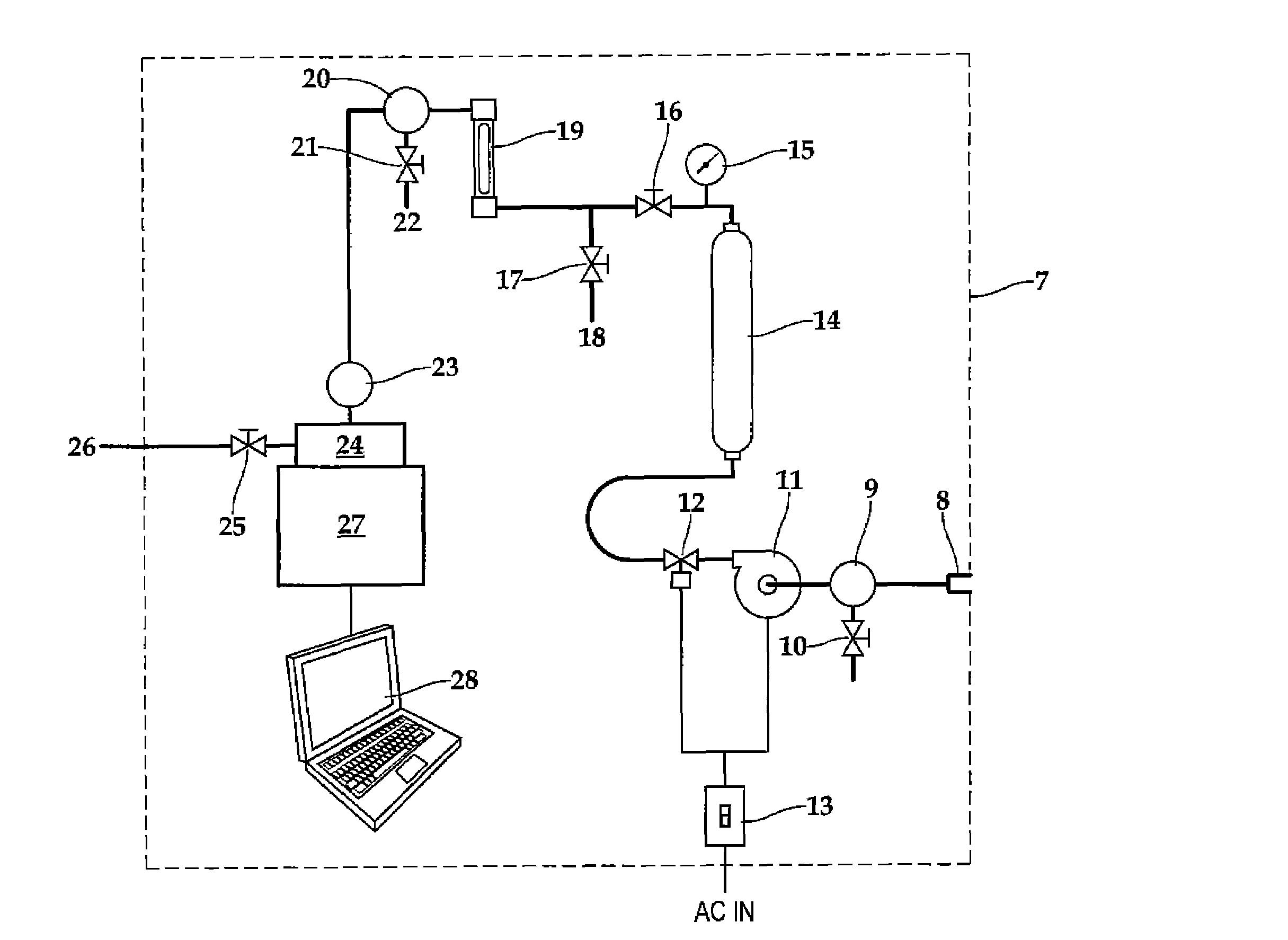
[0049]The present invention is a system and method specifically designed for dealing with natural gas at low pressure (less than 5 psig) or under vacuum. The invention compresses the natural gas to sufficient levels to work in a sample system, such as a gas analyzer (for example, a gas chromatograph). As explained more fully below, the invention incorporates a number of filters to segregate liquids (including water) from the natural gas stream and also to prevent undesired particles from entering the gas analyzer.

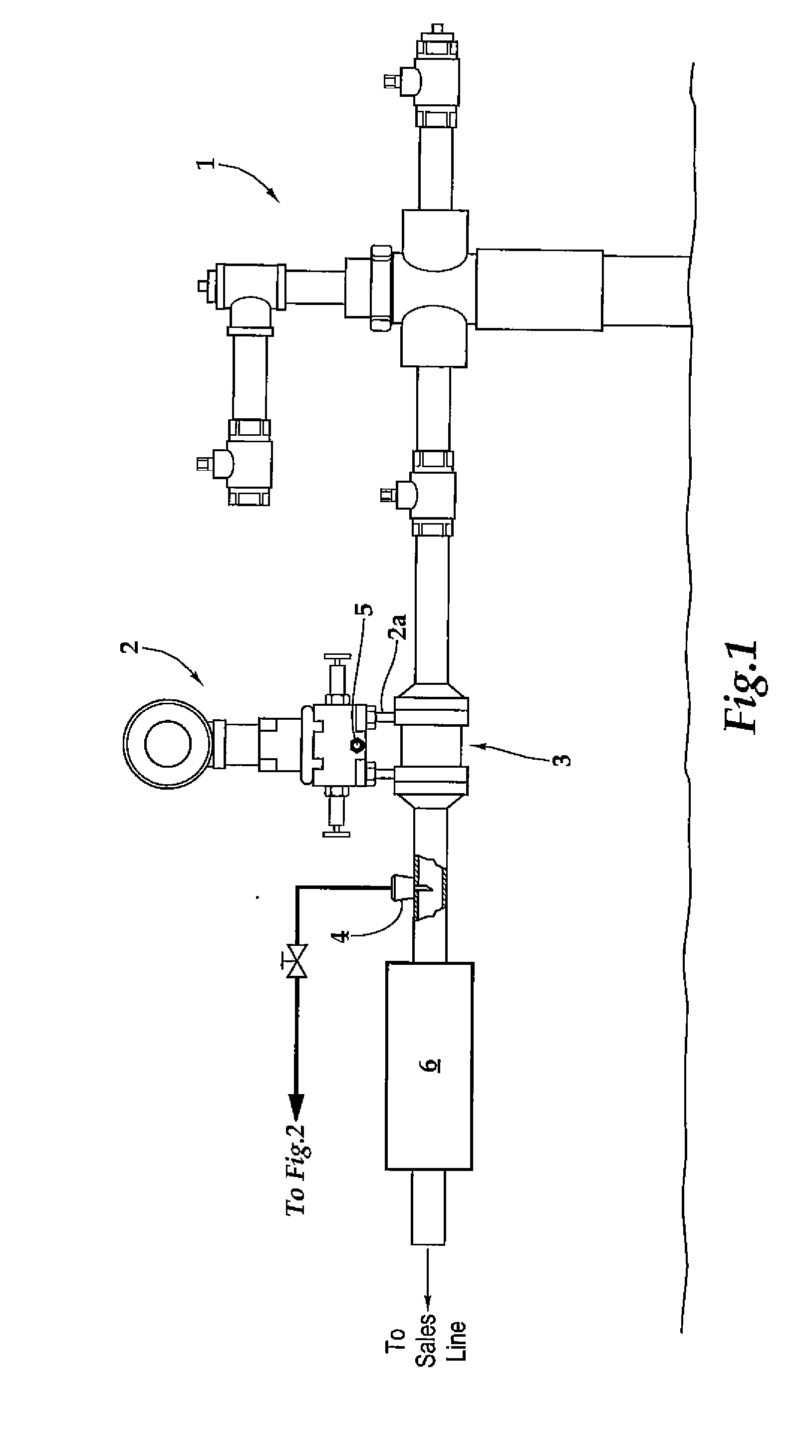
[0050]FIG. 1 is a diagram that shows the relation of the present invention to the wellhead. In this figure, an electronic flow computer 2 is shown downstream of the wellhead 1. A primary flow element 3 is typically situated directly underneath the secondary flow element 2a and tertiary flow element (or electronic flow computer) 2. The manifold 5 is used to isolate the primary flow element 3 and the secondary flow element 2a when calibrating the measurement system. In the co...


PUM


Abstract

A mobile vacuum sampling system comprising: an inlet; a first filter; a gas sample vacuum pump; a solenoid valve; a sample tube; a pressure gauge; a first block valve; a second filter; a micro filter; a gasifier; a gas analyzer; and a computational, recording and / or analysis display device; wherein a natural gas stream enters the gas sample vacuum pump via the inlet and is compressed to between 3 and 5 psig; wherein the sample tube collects natural gas to be analyzed; wherein the gas analyzer is portable; wherein the gas analyzer analyzes gas samples from the sample tube; and wherein the entire system is contained within a truck or other mobile unit.

Description

BACKGROUND OF THE INVENTION[0001]1. Field of the Invention[0002]The present invention relates generally to the field of fluid sampling, and more specifically, to a mobile sampling system for taking samples from a natural gas well that is at low pressure (less than 5 psig) or under vacuum and analyzing those samples in the field.[0003]2. Description of the Related Art[0004]In most cases, after years of production, the amount of natural gas available for production from a given well will decrease. The rate and quantity of the decrease will vary from well to well, but for many wells, it eventually becomes necessary to lower the pressure (to less than 5 psig) or place the well under vacuum in order to cause the natural gas to flow out of the well. In order to lower the pressure or place the well under vacuum, compressors, pumps and / or blowers are added to the pipeline system downstream of the wellhead electronic flow meter. Typically, the well operator can take a sample from the natural...

Claims


Application Information

Patent Timeline
Patent Type & Authority Applications(United States)
IPC IPC(8): E21B49/08
CPCE21B49/084E21B49/008
Inventor MOORE, TROYRHINESMITH, R. BRETCULP, TIMPRICE, GEORGE R.
Owner RHINESMITH R BRET
Why Eureka
Try Eureka