

Solar cell module and method of manufacturing the same
a solar cell and module technology, applied in the field of solar cell modules, can solve the problems of solar cells becoming vulnerable to defects, solar cells becoming vulnerable to such defects, breakage, cracks and microcracks, etc., and achieve the effect of preventing contact failure, preventing occurrence of defects such as cracks, cracks, and microcracks of solar cells
- Summary
- Abstract
- Description
- Claims
- Application Information
AI Technical Summary
Benefits of technology
Problems solved by technology
Method used
Image

Examples
first embodiment
[0047]First, a solar cell module 1 according to a first embodiment of the present invention will be described with reference to FIGS. 2 to 5.
(Configuration of Solar Cell Module)
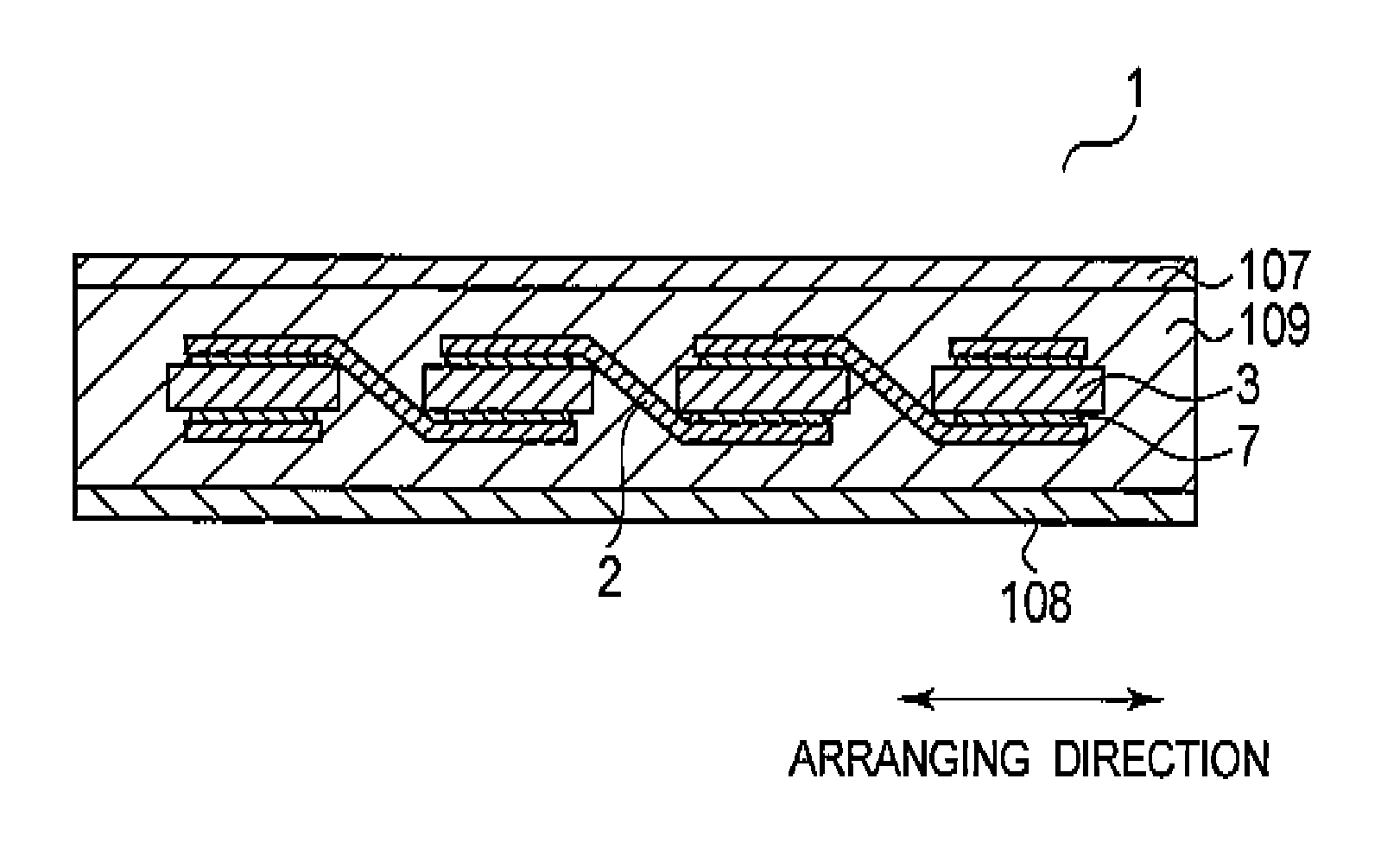
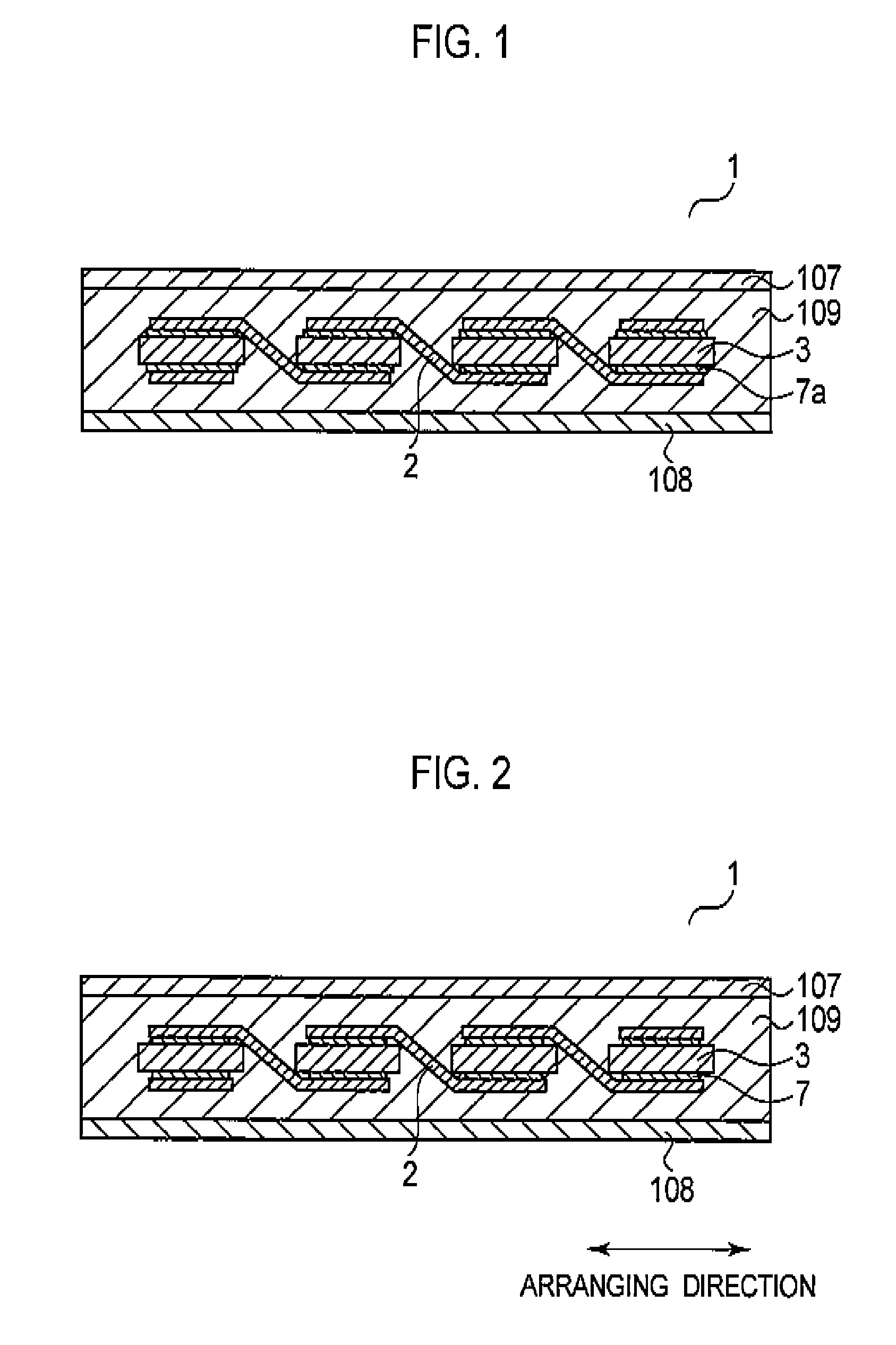
[0048]FIG. 2 is a conceptual cross-sectional view showing a configuration of the solar cell module 1 according to this embodiment. The solar cell module 1 includes a plurality of solar cells 3, 3, . . . electrically connected to each other by wiring members 2, a front surface protection member 107, a sealing member 109, and a back surface protection member 108. The plurality of solar cells 3, 3, . . . is arranged in a arranging direction.
[0049]The wiring members 2 are made of a metal material such as copper. The surface of the wiring members 2 may be the metal material exposed thereon; alternatively, the surface of the wiring members 2 may be covered by a conductive material layer. The wiring members 2 are wound around a reel in advance, and those cut every predetermined length are used as appropriate, accord...
second embodiment
[0072]A second embodiment of the present invention will be described with reference to FIGS. 7A and 7B, FIGS. 8A and 8B and FIG. 9. In the following descriptions, descriptions of the same or similar parts as those in the first embodiment described above will be omitted.
(Solar Cells)
[0073]FIG. 7A and 7B are plane views of a solar cell 32 according to a second embodiment viewed from a light receiving surface side and from the back surface side, respectively. As shown in FIG. 7A, only thin line-shaped electrodes 42A each collecting carriers are formed on the light receiving surface of the solar cell 32. In addition, as shown in FIG. 7B, only thin line-shaped electrodes 412A each collecting carriers are formed on the back surface of the solar cell 32. In addition, parts of the thin line-shaped electrodes 42A and 412A also functions as a connecting electrode for making an electrical connection with wiring member 2. Additionally, the thin line-shaped electrodes 42A and 412A extend in the ...
third embodiment
[0085]A third embodiment of the present invention will be described with reference to FIGS. 10A and 10B, FIGS. 11A and 11B and FIG. 12. In the following descriptions, descriptions of the same or similar parts as those in the first and second embodiments described above will be omitted.
(Solar Cells)
[0086]FIG. 10A is a plane view of a solar cell 33 according to this embodiment viewed from the light receiving surface side, and FIG. 10B is a plane view viewed from the back surface side.
[0087]This embodiment differs from the second embodiment in that crossing electrodes 43B and 413B are provided so that the electrodes 43B and 413B are electrically connected to a plurality of thin line-shaped electrodes 43A or 413A.
(Bonding of Wiring Members)
[0088]FIG. 11A is a view of the solar cells viewed from the light receiving surface side for illustrating a connection relationship of the crossing electrodes 43B, thin line-shaped electrodes 43A, and the bonding layers 7a. FIG. 11B is an enlarged vie...
PUM
| Property | Measurement | Unit |
|---|---|---|
| thickness | aaaaa | aaaaa |
| thickness | aaaaa | aaaaa |
| thickness | aaaaa | aaaaa |
Abstract
Description
Claims
Application Information