
Transmitting and receiving apparatuses and methods

a technology of transmitting and receiving apparatus and methods, applied in multiplex communication, orthogonal multiplex, frequency-division multiplex, etc., can solve the problems of relative deterioration of channel estimation accuracy in mbms channel, and worse communication environment, so as to improve the receive quality of mbms channel

Active Publication Date: 2009-08-06
NTT DOCOMO INC
View PDF4 Cites 60 Cited by
  • Summary
  • Abstract
  • Description
  • Claims
  • Application Information

AI Technical Summary

Benefits of technology

The present invention aims to improve the receive quality of the MBMS channel by providing a transmitting apparatus that transmits a transmit symbol in the OFDM scheme. The transmitting apparatus includes a unicast channel, a MBMS channel, a specific pilot channel, and one or more common pilot channels. The multiplexing unit time-division multiplexes the unicast frame and the MBMS frame, with the insertion density of the common pilot channel being larger than the insertion density of the specific pilot channel. This results in a transmit symbol with improved receive quality for the MBMS channel.

Problems solved by technology

However, if the unicast channel is merely replaced by the MBMS channel (if the scrambling code which differs from cell to cell is used for transmitting the MBMS channel), the user apparatus has to perform the process as described above while identifying a signal from a surrounding base station (specifically, a pilot channel), which is difficult.
Thus, the channel estimation accuracy in the MBMS channel may deteriorate relative to the same for the unicast channel.
For example, when a user apparatus is moving at high speed, the communications environment becomes worse.

Method used


Image

  • Transmitting and receiving apparatuses and methods
  • Transmitting and receiving apparatuses and methods
  • Transmitting and receiving apparatuses and methods

Examples


embodiment 1

[0049]In the embodiment below, while a system is explained which adopts the orthogonal frequency divisional multiplexing (OFDM) scheme for downlink, the present invention may be applied to other multi-carrier systems.

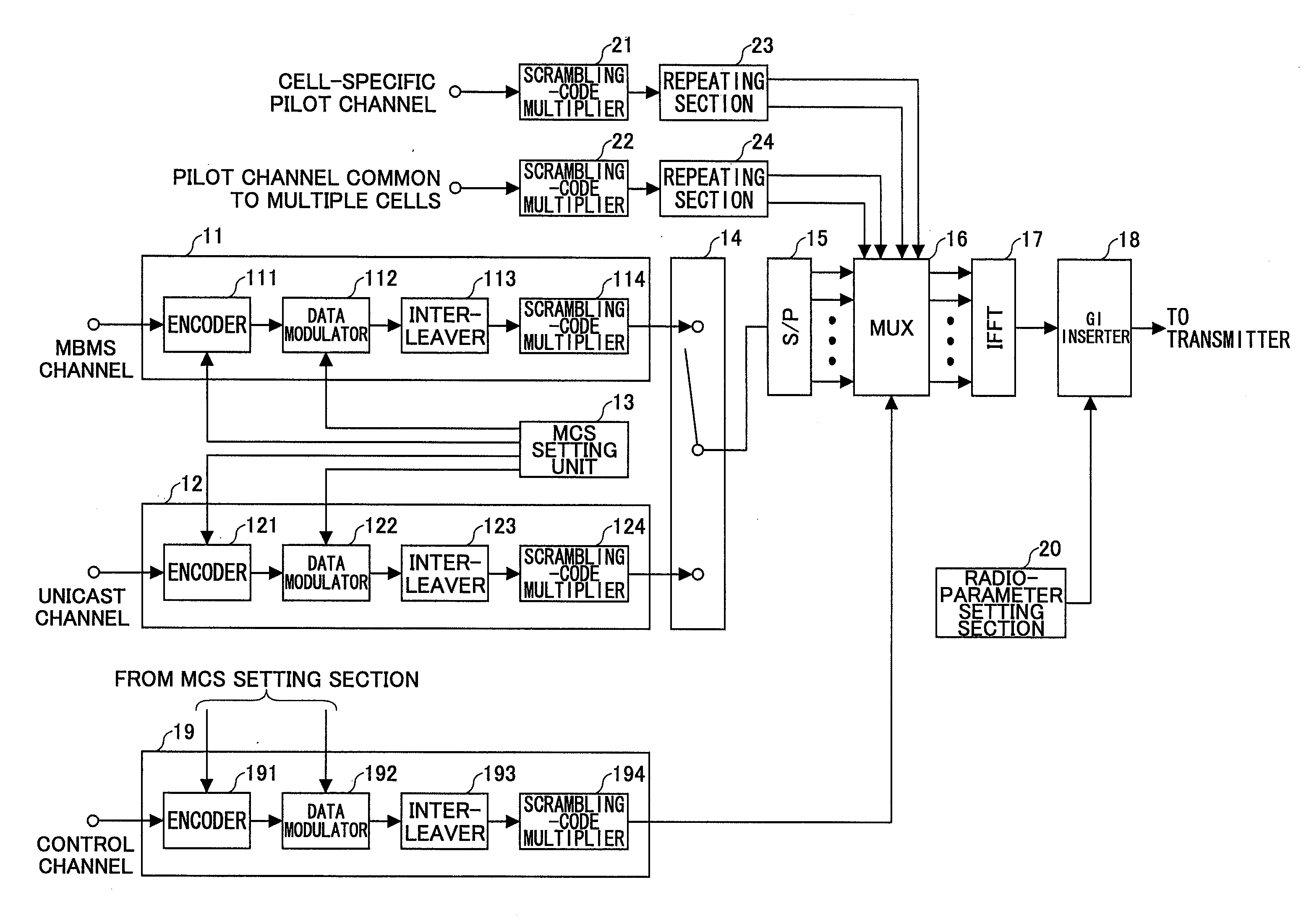
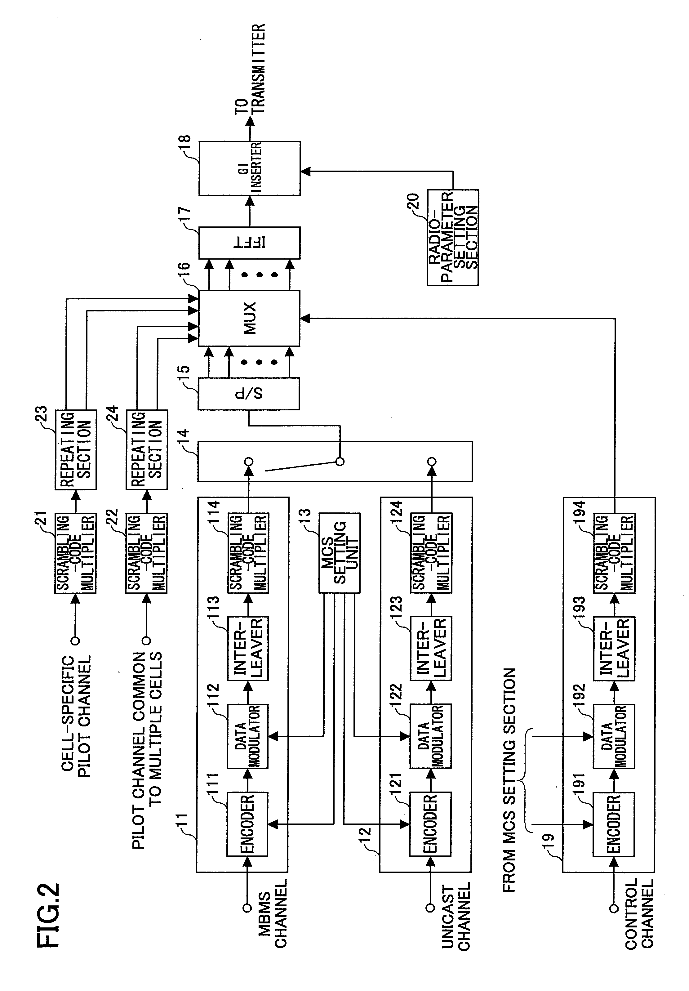
[0050]FIG. 2 is a schematic block diagram of a transmitter according to an embodiment of the present invention. While the transmitter is typically provided at a base station, as in the present embodiment, it may be provided at another apparatus. FIG. 2, which illustrates the transmitter, shows an MBMS processor 11, a unicast channel processor 12, an MCS setting section 13, a control channel processor 19, a first multiplexer 14, a serial / parallel converter (S / P) 15, a second multiplexer (MUX) 16, an inverse fast Fourier transformer (IFFT) 17, a guard interval inserter 18, a radio-parameter setting section 20, a scrambling code multiplier 21, 22, and repeating sections 23, 24. The MBMS processor 11 includes an encoder 111, a data modulator 112, an interleaver 113, and a s...

embodiment 2

[0090]As described above, the unicast and MBMS frames are time-division multiplex transmitted, with the unicast channel channel-compensated using a specific pilot channel included in the unicast frame and the MBMS channel channel-compensated using a common pilot channel included in the MBMS frame. Thus, with respect to the objective of channel compensating the MBMS channel, the specific pilot channel does not have to be inserted into the MBMS frame.

[0091]On the other hand, a user apparatus measures the downlink receive quality in predetermined periods (CQI measurement periods), and reports the measured value to the base station. The receive quality may be expressed in various channel quality indicators (CQI) including SNR, SIR, and SINR. The base station schedules (allocate wireless resources to, determine modulation scheme and channel coding rate, and determine transmit power) a unicast channel to be transmitted next based on the CQI measurement value. Thus, a specific pilot channe...

embodiment 3

[0098]FIG. 7 is a schematic block diagram of a receiver according to an embodiment of the present invention. Such a receiver as described above is typically provided at a user apparatus such as a mobile station. FIG. 7 illustrates a receiver, including a symbol timing detector 520, a guard interval (GI) remover 522, a fast Fourier transformer 524, a demultiplexer 526, a channel estimator 528, a channel compensator 530, a parallel / serial (P / S) converter 532, a channel compensator 534, a deinterleaver 536, a turbo decoder 538, a Viterbi decoder 540, and a radio-parameter setting section 542.

[0099]The symbol timing detector 520 detects a symbol (symbol boundary) timing based on a received signal. The received signal is a signal after undergoing reception, amplification, frequency conversion, bandwidth limiting, orthogonal demodulation, and conversion-to-digital processes.

[0100]The GI remover 522 removes, from the received signal, a portion corresponding to the GI.

[0101]The fast Fourier...


PUM


Abstract

A transmitting apparatus which transmits a transmit symbol in orthogonal-frequency division multiplexing (OFDM) is disclosed. The transmitting apparatus includes a unit which provides a unicast channel; a unit which provides a multimedia broadcast multicast service (MBMS) channel; a unit which provides a specific pilot channel which is specific to a specified cell; a unit which provides one or more common pilot channels common to a plurality of cells; and a multiplexing unit which multiplexes the unicast channel, the MBMS channel, the specific pilot channel, and the one or more common pilot channels, and creates the transmit symbol, wherein the multiplexing unit time-division multiplexes, in the same frequency band, a unicast frame which includes the unicast channel, and an MBMS frame which includes the MBMS channel, and wherein an insertion density of the common pilot channel included in the MBMS frame is larger than an insertion density of the specific pilot channel included in the unicast frame.

Description

BACKGROUND OF THE INVENTION[0001]1. Field of the Invention[0002]The present invention relates generally to a technical field of wireless communications and more specifically to apparatuses and methods which transmit and receive a multimedia-broadcast multicast service (MBMS) channel.[0003]2. Description of the Related Art[0004]In next-generation mobile communications systems in which video and data communications are primarily conducted, capabilities far surpassing those of the third generation mobile communications system (IMT-2000) are called for, necessitating a sufficient realization of broadband, and increased capacity and speed in communications. Therefore, various outdoor and indoor communications surroundings are envisaged. In downlink data transmissions, not only a unicast scheme, but also multicast and broadcast schemes are conducted. More specifically, an increasing importance has been placed on transmitting an MBMS channel in recent years. The MBMS channel includes multi...

Claims


Application Information

Patent Timeline
Patent Type & Authority Applications(United States)
IPC IPC(8): H04J11/00H04L27/28H04H20/71H04J1/00
CPCH04J11/0079H04L5/0007H04W72/005H04L5/005H04L5/0051H04L5/003H04W72/30H04L27/26134
Inventor MORIMOTO, AKIHITOKISHIYAMA, YOSHIHISAMIKI, NOBUHIKOHIGUCHI, KENICHISAWAHASHI, MAMORU
Owner NTT DOCOMO INC
Learn More