
Systems and Methods for On-Site Selective Catalytic Reduction

a selective catalytic and system technology, applied in the direction of machines/engines, bulk chemical production, arsenic compounds, etc., can solve the problems of smog, smog is a significant form of air pollution, and substances that are harmful to the environmen

Inactive Publication Date: 2009-08-06
CERAMTEC
View PDF10 Cites 7 Cited by
  • Summary
  • Abstract
  • Description
  • Claims
  • Application Information

AI Technical Summary

Benefits of technology

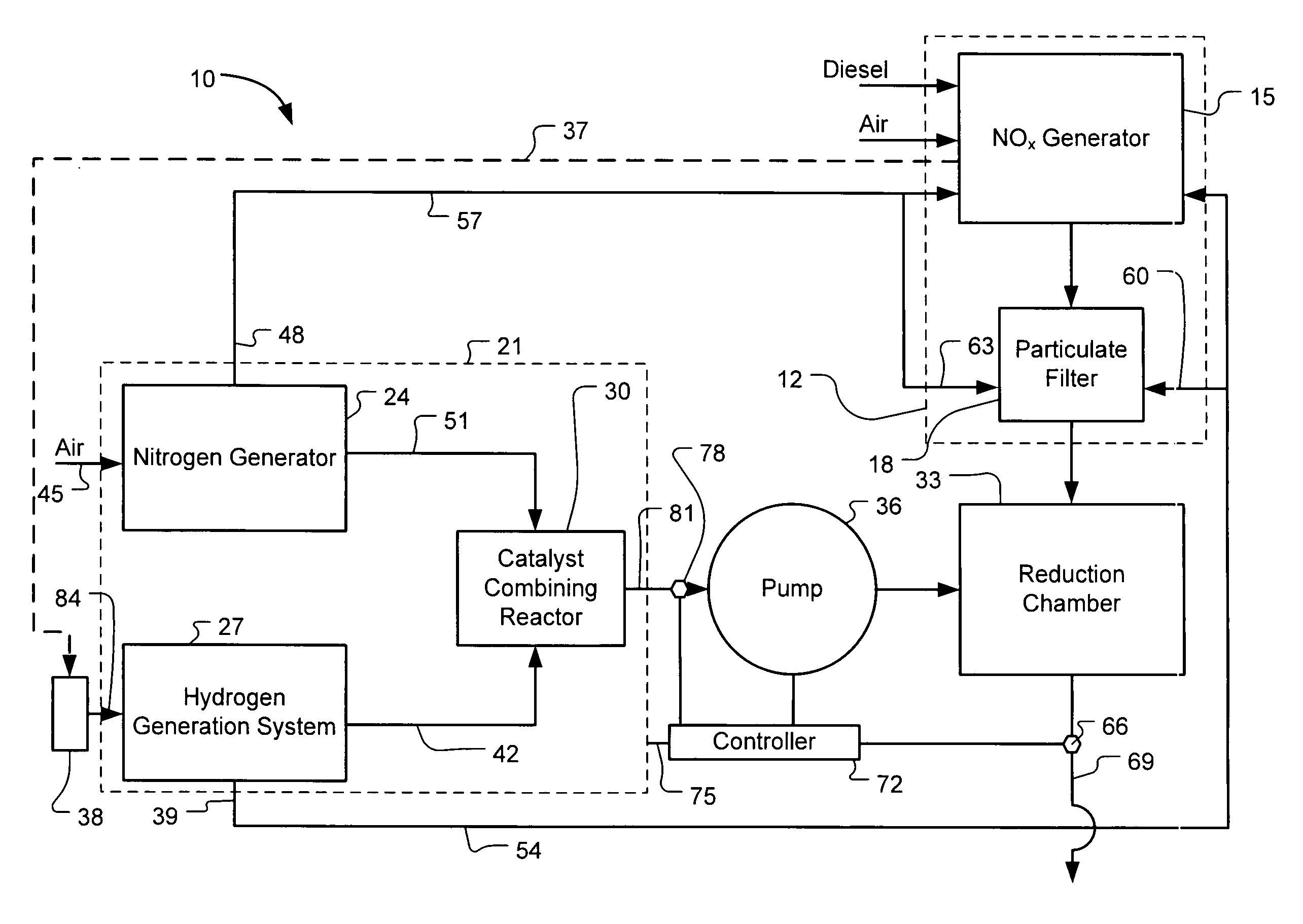
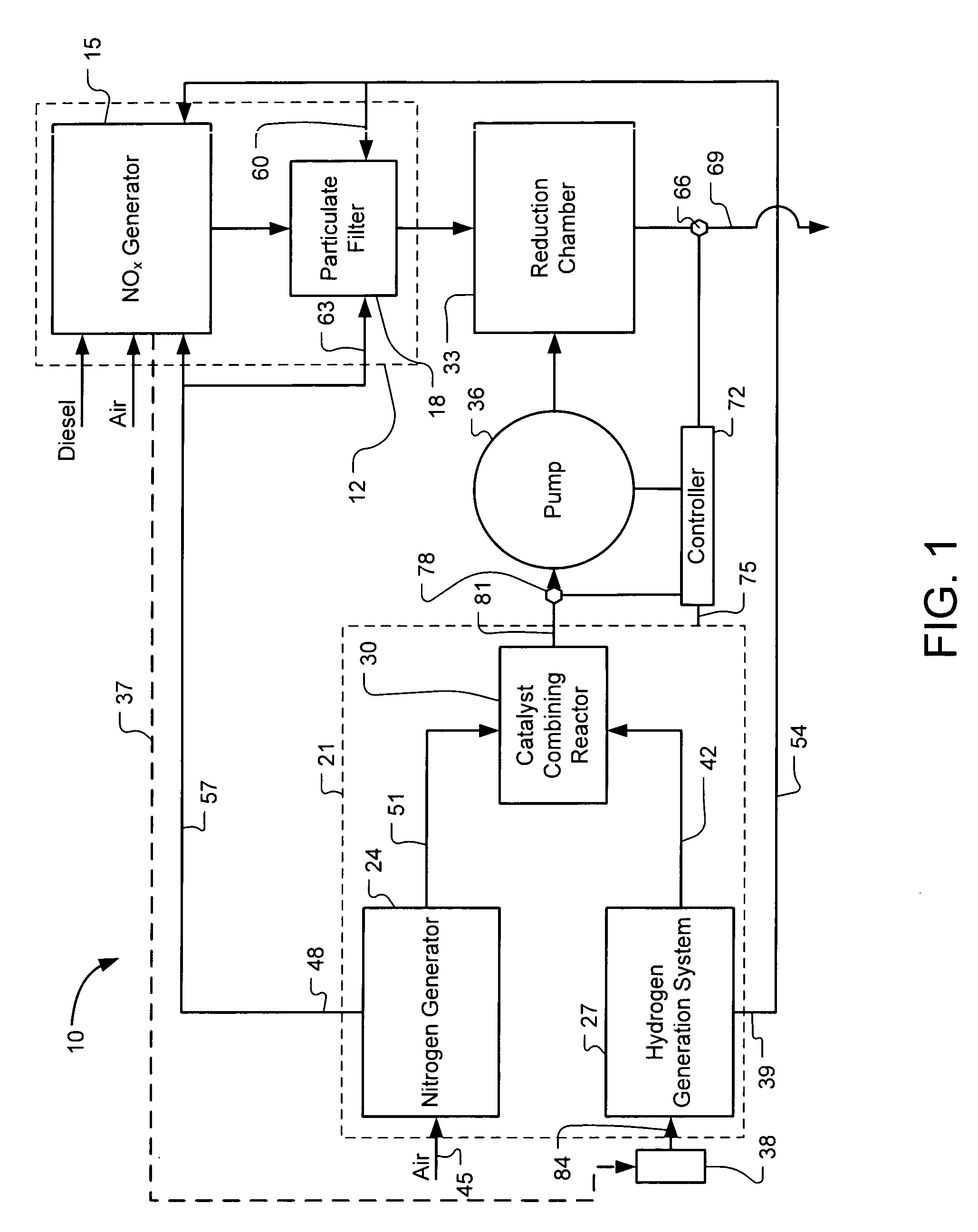
[0005]Embodiments of a system are described. In one embodiment the system is a selective catalytic reduction (SCR) system. An embodiment of the SCR system includes a NOx generator and an on-board ammonia product generation system. The on-board ammonia product generation system includes a nitrogen generator coupled to an air intake and a hydrogen generation cell coupled to a source of a hydrogen-containing compound. The on-board ammonia product generation system also includes a catalyst combining reactor coupled to each of the nitrogen generator and the hydrogen generation cell. The SCR system also includes a reduction chamber coupled to each of the NOx generator and the on-board ammonia product generation system. The reduction chamber is configured to receive on-board generated ammonia product from the catalyst combining reactor and from the NOx generator for conversion of the NOx into at least H2O and nitrogen.

Problems solved by technology

Combustion engines, such as those used in power plants and motor vehicles, emit substances that are harmful to the environment, including nitrogen oxide.
Nitrogen oxides such as nitric oxide (NO) and nitrogen dioxide (NO2) are extremely toxic.
This smog is a significant form of air pollution, especially in the summertime.
Children, people with lung diseases, such as asthma, and people who work or exercise outside are susceptible to adverse effects of smog such as damage to lung tissue and reduction in lung function.
As is well known, acid rain causes negative visual and physical affects to buildings and other structures.
Furthermore, any unnatural level of nitric acid in the environment due to acid rain is undesirable.

Method used


Image

  • Systems and Methods for On-Site Selective Catalytic Reduction
  • Systems and Methods for On-Site Selective Catalytic Reduction
  • Systems and Methods for On-Site Selective Catalytic Reduction

Examples


Embodiment Construction

[0013]In the following description, specific details of various embodiments are provided. However, some embodiments may be practiced with less than all of these specific details. In other instances, certain methods, procedures, components, structures, and / or functions are described in no more detail than to enable the various embodiments of the invention, for the sake of brevity and clarity.

[0014]Although certain functionality is described herein with respect to each of the illustrated components of the selective catalytic reduction (SCR) system, other embodiments of the SCR may implement similar functionality using fewer or more components. Additionally, some embodiments of the SCR may implement more or less functionality than is described herein.

[0015]FIG. 1 illustrates a schematic block diagram of an embodiment of the selective catalytic reduction (SCR) system 10. The SCR system 10 includes a NOx source 12 having a NOx generator 15 and a particular filter 18. A NOx generator 15 a...


PUM

PropertyMeasurementUnit
temperaturesaaaaaaaaaa

Abstract

A selective catalytic reduction (SCR) system includes an on-board ammonia generation system that produces nitrogen from air and hydrogen from a source of a hydrogen-containing compound, and generates an ammonia product from the nitrogen and hydrogen to provide the ammonia product into an exhaust from a NOx generator to reduce the NOx in the exhaust. Oxygen from one or both of the nitrogen generator and the hydrogen generation cell can be supplied to the NOx generator for cleaner combustion or to a particulate filter for cleaning the filter. H2O from the NOx generator can at least partially provide a water source for the hydrogen generation cell.

Description

BACKGROUND[0001]Combustion engines, such as those used in power plants and motor vehicles, emit substances that are harmful to the environment, including nitrogen oxide. Nitrogen oxides such as nitric oxide (NO) and nitrogen dioxide (NO2) are extremely toxic. Nitric oxide and nitrogen dioxide are often present when nitrous oxide (N2O) is produced during combustion.[0002]When NOx and volatile organic compounds react in the presence of sunlight they form photochemical smog. This smog is a significant form of air pollution, especially in the summertime. Children, people with lung diseases, such as asthma, and people who work or exercise outside are susceptible to adverse effects of smog such as damage to lung tissue and reduction in lung function. Also, NOx forms nitric acid when dissolved in atmospheric moisture, forming a component of acid rain. As is well known, acid rain causes negative visual and physical affects to buildings and other structures. Furthermore, any unnatural level ...

Claims


Application Information

Patent Timeline
Patent Type & Authority Applications(United States)
IPC IPC(8): B01D53/56B01J19/24B01D53/86
CPCB01D53/90B01D53/9431B01D2251/2062B01D2258/012C01C1/0488C01B3/38C01B2203/0205C01B2203/1247C01C1/0405C01B3/342Y10S423/05Y02P20/52
Inventor JOSHI, ASHOK V.
Owner CERAMTEC
Learn More