
Producing a flexographic printing plate

Inactive Publication Date: 2009-08-06
FFEI LTD
View PDF4 Cites 63 Cited by
  • Summary
  • Abstract
  • Description
  • Claims
  • Application Information

AI Technical Summary

Benefits of technology

[0015]characterized by additionally curing one or more lower printed layers before or while printing one or more upper layers so as to reduce spreading of the lower printed layer(s).
[0020]a second curing system for additionally curing one or more lower printed layers before or while printing upper layers so as to reduce spreading of the lower printed layers.
[0021]We have developed a number of improved methods for producing flexographic printing plates which reduce or avoid the spreading problem set out above by introducing an additional curing stage for at least some of the lower printed layers.
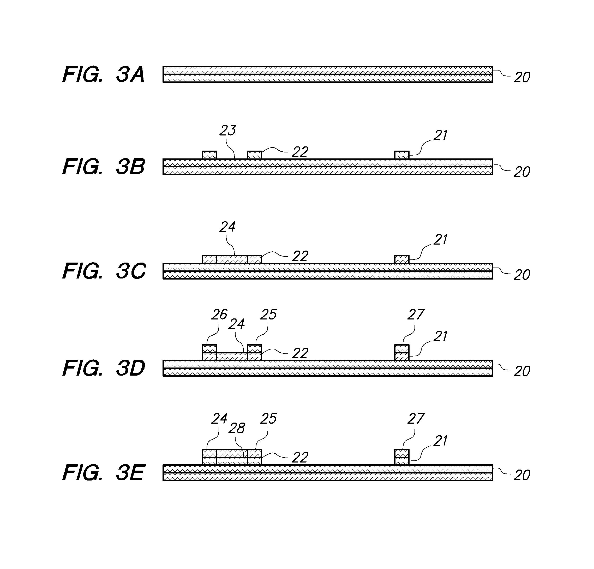
[0024]In another approach, step (a) comprises printing edges of the predetermined pattern, the method further comprising a step (d) between steps (b) and (c) in which flexographic material is inkjet printed into areas defined by the printed edges whereby additional curing of the edges is achieved by implementing step (c) to repeat steps a, b, and d. The advantage of this is that a separate curing system for the additional curing step is not necessary since the system for curing at step (b) is used.
[0026]The finished form of the raised portions of the flexographic printing plate is important to achieve a high quality printed image in use. An important aspect of the finished form is the shape of the upwardly facing surface of each dot or other feature on the plate. US-A-2004 / 0131778 describes a method for improving the surface quality by depositing small drops of flexographic material on to the surface. However, this requires additional material and accurate printing resolution.

Problems solved by technology

The manufacture of flexographic plates is a relatively slow process since it involves several manufacturing stages.
This process has a number of drawbacks in that it is very labour intensive, it has high environmental impact in that the removed material needs to be disposed of, and the time taken for all these stages is slow.
Another drawback to this process is that areas with large solid tints require high pressures that contact point between paper and plate to ensure good ink transfer over the whole of the print area and leave no missing print areas or pin holes in the printed region.
The high print pressure require for large solid tints is not desirable for the toned areas though as in the tonal regions the high pressure causes distortion of the raised printing surface and unwanted dot growth occurs.
A problem with this technique is that although each layer is pin cured or immobilized, it has been found that firstly the pin curing or immobilizing will not remain in effect for the time taken to print the upper layers and secondly, due to the weight of the upper layers, some lateral spreading of the lower layers or “creep” will occur.
This will result in a derogation in the image which is finally printed using the printing plate.
This fill material is then removed in a further processing stage, but this is undesirable as it produces additional waste which needs to be correctly disposed of and adds time to the overall manufacturing process.

Method used


Image

  • Producing a flexographic printing plate
  • Producing a flexographic printing plate
  • Producing a flexographic printing plate

Examples


Embodiment Construction

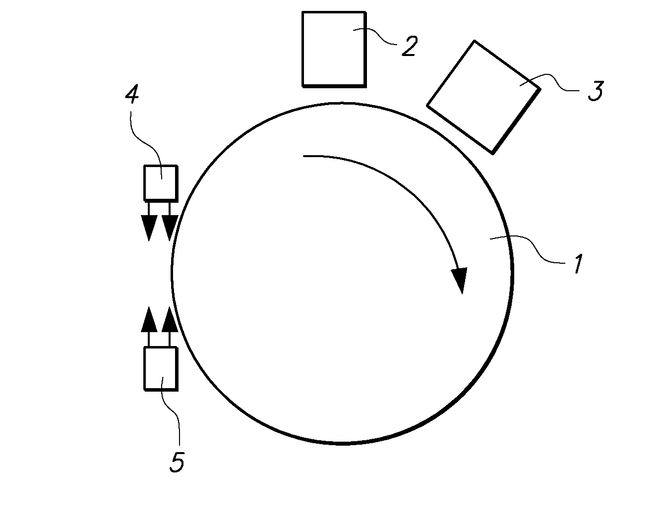
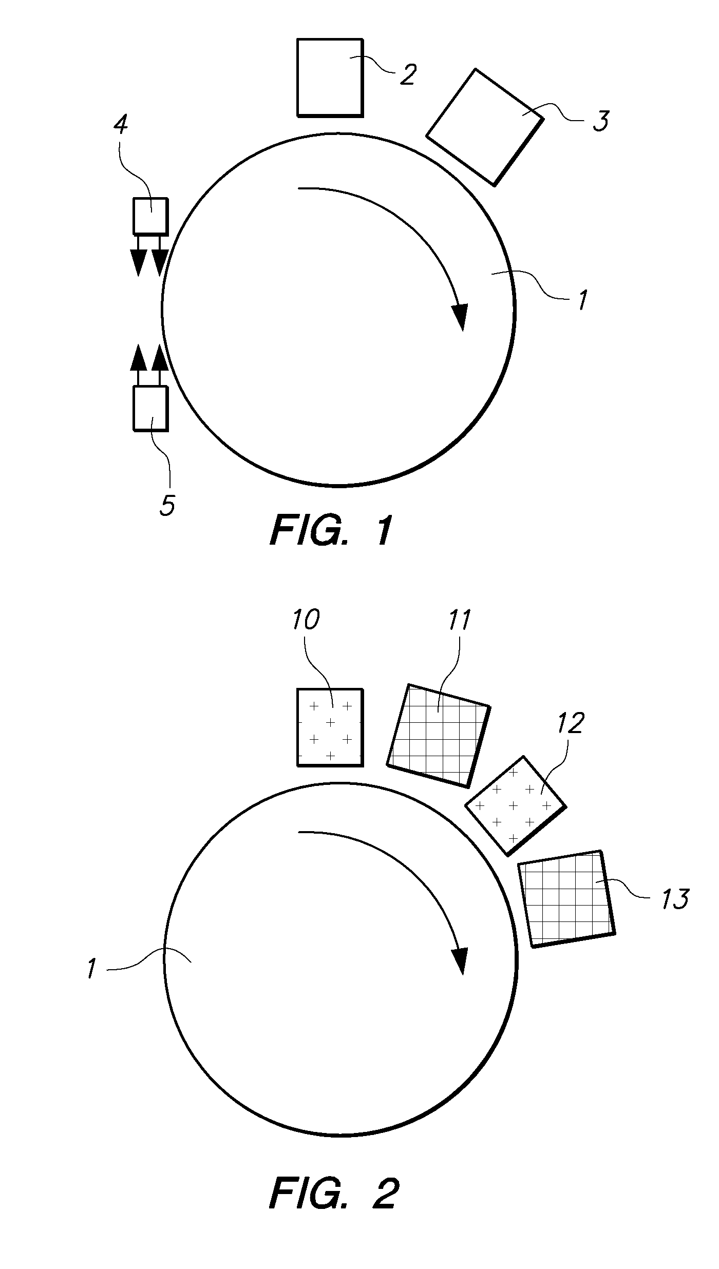
[0038]In the first example of apparatus according to the invention shown in FIG. 1, a rotatably mounted drum 1 is provided on which a printing plate (not shown) is mounted in use. The drum rotates in a clockwise direction in use so as to cause the plate to pass firstly under an inkjet printer 2 having an inkjet print bar which is controlled to print a flexographic material in a predetermined pattern on to the plate; and then under a pin curing device 3, typically a source of UV-C radiation. Further rotation of the drum 1 brings the plate into the vicinity of further UV-C sources 4, 5 which are arranged, as explained below, to irradiate sides of the material printed by the inkjet printer 2 so as to additionally cure the side walls. The drum 1 then further rotates to bring the plate back under the inkjet printer 2 to enable a further layer of flexographic material to be printed on to the previously printed layer. This process continues until the plate has been fully printed at which p...


PUM


Abstract

A method of producing a flexographic printing plate, comprises:a) inkjet printing a layer of flexographic material in a predetermined pattern onto a substrate;b) partially curing at least part of the printed layer of flexographic material so as to immobilize it on the substrate; andc) repeating steps (a) and (b) so as to print and partially cure one or more further layers of flexographic material in the predetermined pattern on the previous layer(s),characterized by additionally curing one or more lower printed layers before or while printing one or more upper layers so as to reduce spreading of the lower printed layer(s).

Description

FIELD OF THE INVENTION [0001]The invention relates to methods and apparatus for producing a flexographic printing plate.DESCRIPTION OF THE PRIOR ART [0002]Flexographic printing plates are used widely in letter press printing and the like, particularly for printing on surfaces which are soft and easily deformable such as packaging materials. The plates are typically prepared from photopolymerizable compositions comprising an elastomeric binder, at least one monomer and a photo-initiator.[0003]The manufacture of flexographic plates is a relatively slow process since it involves several manufacturing stages. A plate is typically made from three layers. A UV transparent support layer, a layer of uncured flexographic material such as rubber, and an upper light sensitive UV mask material. The light sensitive UV mask is exposed to UV-A irradiation with the print image required, and developed. Then the flexographic material is exposed with UV-A Light from the rear and above to cure the area...

Claims


Application Information

Patent Timeline
IPC IPC(8): B05B5/025B05D1/36B05D3/06
CPCB41C1/003
Inventor GOUCH, MARTIN PHILIPBITTNER, CHRISTOPH
Owner FFEI LTD
Learn More