
Multifunctional Residential Circuit Breaker

a multi-functional, residential technology, applied in emergency protective circuit arrangements, instruments, etc., can solve the problems of low-voltage arcing, a significant fire hazard, and a high probability of dangerous arcing in the home, so as to quickly and effectively discriminate arc faults

Active Publication Date: 2009-08-06
SIEMENS IND INC
View PDF5 Cites 77 Cited by
  • Summary
  • Abstract
  • Description
  • Claims
  • Application Information

AI Technical Summary

Benefits of technology

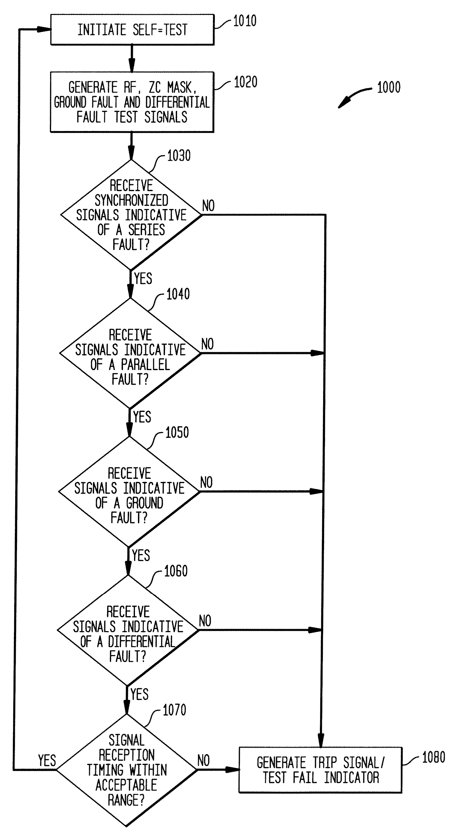
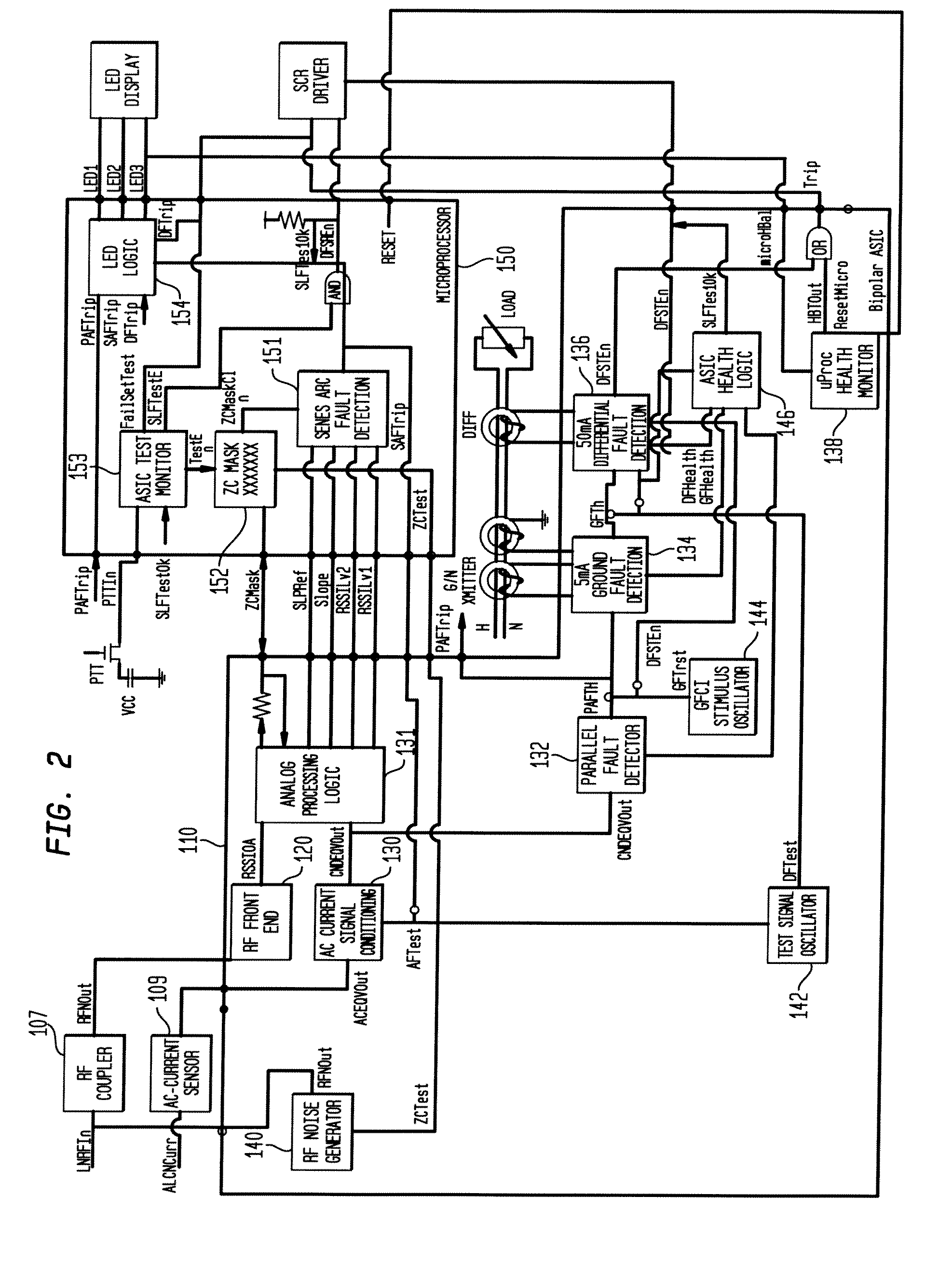
[0017]Processes and methods consistent with the disclosed embodiments are directed toward an arc-fault circuit interrupter (AFCI) device that can quickly and effectively discriminate arc-faults from broadband signal sources. Alternatively and / or additionally, the disclosed embodiments may be directed toward a combination AFCI / GFCI device that provides fault detection, mitigation, and reporting of both arc faults and ground faults for an electrical system in a single, integrated module. Additionally, certain disclosed embodiments are directed toward a self-monitoring system and method associated with the AFCI and / or the AFCI / GFCI combination device that enables the device to analyze itself based on predetermined operating criteria. The self-monitoring system may be adapted to provide a health status indication that reports the results of the self-monitoring analysis.
[0025]In accordance with yet another aspect, the present disclosure is directed toward methods and processes that are configured to detect and interrupt arc fault conditions to potentially mitigate certain effects of these conditions such as fires or property damage. These methods are adapted to not only detect these conditions under a wide range of normal operating scenarios but also effectively avoid shortcomings that may limit existing methods of arc determination such as, for example, false identification of non-arcing conditions as arcing conditions (e.g., power line communication schemes like Homeplug® or other broadband power line (BPL) communication systems), false identification of arcing conditions as non-arcing conditions (e.g., “masking” loads that can sometimes change the characteristics in the line enough to affect the performance the arc detection system), and sudden increases in broadband noise due to certain loads (e.g., “cold” start of dimmer switches, arcing due to commutation of brushes in certain appliances, etc.).

Problems solved by technology

Electrical arcs can develop temperatures well above the ignition level of most common flammable materials and, therefore, pose a significant fire hazard.
Fortunately, low-voltage arcing is an inherently unstable phenomenon and does not usually persist long enough to start a fire.
Two types of dangerous arcing that are likely to occur in the home are momentary, high-energy arcs caused by high-current faults and persistent, low-current “contact” arcing.
A high-current fault, caused by an inadvertent direct connection between line and neutral or line and ground, will generally draw current up to or beyond the rated capacity of the circuit, arc explosively as the contacts are physically made and broken, dim lights and other loads indicating an excessive load is being drawn, and / or (assuming the circuit is properly protected by a circuit breaker) trip the breaker, thereby interrupting the current to the arc.
Because such “line faults” are short-lived, the temperature rise in the feed conductors is limited and the fire danger results primarily from the explosive expulsion of minute glowing globules of copper from the contact area which may ignite nearby flammable materials.
Even if a fire begins, however, the high visibility of the fault and the likely presence of someone nearby (who provided the physical impetus to bring the conductors together) sharply mitigates the potential for an uncontrolled fire.
Under certain conditions, such arcing may become persistent and present a substantial fire hazard.
One example of a condition that may cause contact arcing is a well-used wall outlet wherein the spring pressure provided by the contacts has been reduced through age and use, so that insufficient pressure is applied to the inserted plug contacts to ensure low-resistance connection.
Contact arcing is also commonly caused by use of extension cords of insufficient current-carrying capacity.
A third cause of contact arcing often observed in aluminum wiring involves the oxidation of contacts.
However, if the connections become loose over time, oxidation begins and arcing can result.
Contact arcing is also common when the springs that snap switches on or off become worn, increasing the time to closure and reducing the force that holds the contacts together.
Because the center contact is subjected to high temperatures and repeated use, it often becomes loose and oxidizes, thereby increasing the likelihood of arcing.
A common result in very old lamp fixtures is that arcing at the center contact or around the aluminum threads causes the lamp to become welded into the socket and therefore very difficult to remove.
Frayed conductors that come into light or intermittent contact, or staples that inadvertently pierce wire insulation, can produce resistive shorts through contamination and oxide layers, particularly if moisture is present.
Dangerous arcs may begin as small and occasional arcing, gradually building up over time until the arcing becomes persistent enough to start a fire.
“Hard shorts” will generally involve high currents (>50 A) and will be explosive at the fault point contact, so that the fault will either burn itself out or trip a circuit breaker.
Nevertheless, even low-current contact arcing, for example, a 60 watt light bulb on the end of a faulty extension cord, or a set of Christmas tree lights with faulty contacts, may release sufficient heat to cause a fire.
Accordingly, conventional circuit breakers are inadequate to prevent dangerous conditions due to contact arcing.
If not properly identified and rejected, these types of signals, which may be easily confused with arc-fault signals, may cause “nuisance” tripping of certain arc-fault circuit detectors.

Method used


Image

  • Multifunctional Residential Circuit Breaker
  • Multifunctional Residential Circuit Breaker
  • Multifunctional Residential Circuit Breaker

Examples


Embodiment Construction

[0056]Reference will now be made in detail to the exemplary embodiments of this disclosure, examples of which are illustrated in the accompanying drawings. Wherever possible, the same reference numbers will be used throughout the drawings to refer to the same or like parts.

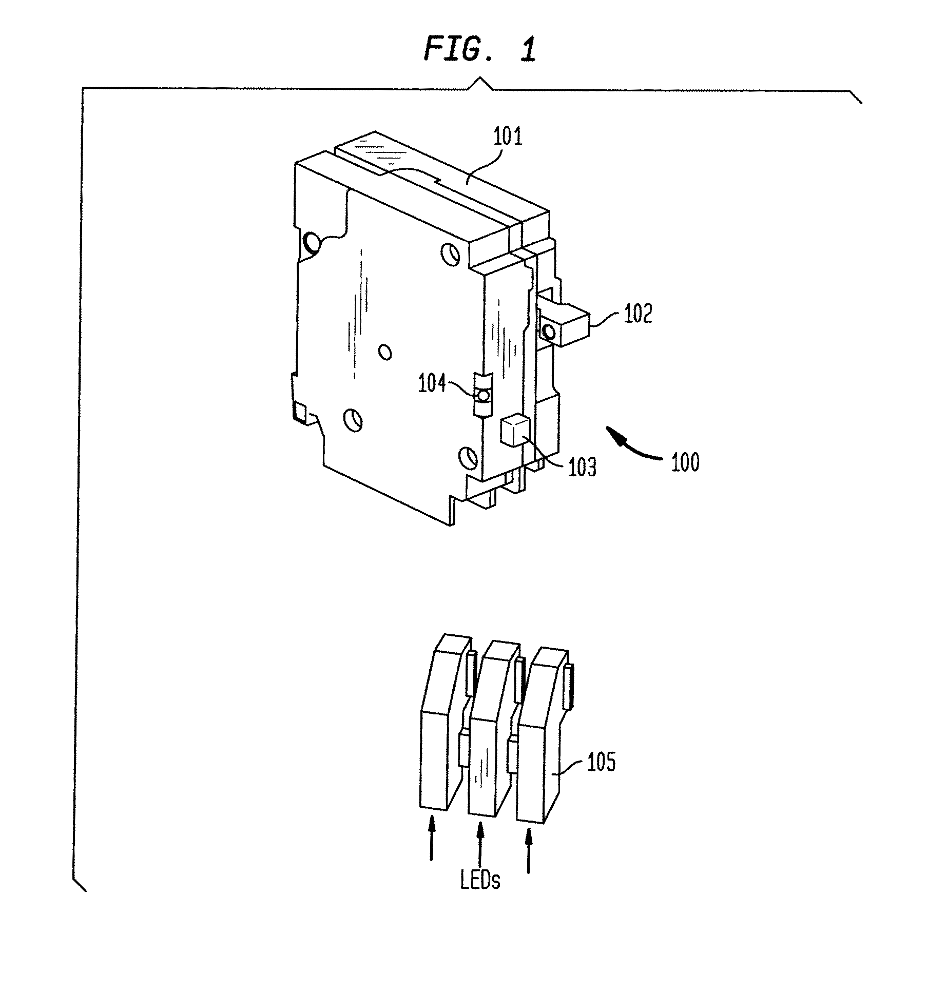
[0057]FIG. 1 provides a diagram of an exemplary arc fault circuit interrupting (AFCI) device 100. This device may be adapted for use in any residential and / or commercial power system environment and may be configured to detect arc faults, including both line-fault (i.e., parallel-type arcing between lines) and contact-fault (i.e., series-type arcing on the same line due to electrical discontinuity in the conductor) that may be present on a power circuit associated with the power system. Device 100 may also be configured to detect ground faults occurring on or otherwise associated with a power distribution circuit. It is contemplated that device 100 may include one or more circuits and subsystems for implementing p...


PUM


Abstract

An electrical fault detection device for use in a branch of a power circuit that utilizes signals from an AC line current sensor coupled to an electrical distribution line having a primary and neutral lines, a line high-frequency sensor coupled to the electrical distribution line, a differential current sensor coupled to the primary and neutral lines, and a ground fault current sensor coupled to the primary and neutral lines. A signal conditioner receives the signals outputted by AC current line current sensor, the line high frequency sensor, the differential current sensor and the ground fault current sensor and generates a signal indicative of the load current associated with a branch of the power circuit. Output of the signal conditioner is sampled and processed by a processing resource. The processing resource has stored therein data representing a plurality of time-versus-current curves that define a plurality of regions in which tripping may or may not occur. One region has time data and current data that define a time-duration for a particular current magnitude for which no tripping will occur. Another region has time data and current data that define a time-duration of a particular current magnitude for which tripping will occur. Processing resource processes sampled signal to determine the region to which the processed time data and current data correspond, and generates a signal to initiate tripping if the sampled signal yields a time duration for a particular current magnitude that corresponds to a region for which tripping must occur.

Description

CROSS-REFERENCE TO RELATED APPLICATIONS[0001]This application is a continuation-in-part of pending U.S. application Ser. No. 11 / 978,969, filed Oct. 30, 2007, now United States Patent Application Publication No. 20080106832, which claims the benefit of U.S. provisional application No. 60 / 855,424, filed Oct. 31, 2006. The entire disclosures of the aforesaid application Ser. Nos. 11 / 978,969 and 60 / 855,424 and publication no. 20080106832 are herein incorporated by reference.[0002]This application also claims priority to and the benefit of the filing date of pending U.S. provisional application No. 61 / 042,916, filed on Apr. 7, 2008, entitled “Multifunctional Residential Circuit Breaker,” the entire disclosure of which is hereby incorporated by reference.TECHNICAL FIELD[0003]The present invention relates generally to fault detection in electrical circuits. More particularly the invention is directed to systems and methods for detecting and mitigating arc faults in electrical systems. The ...

Claims


Application Information

Patent Timeline
Patent Type & Authority Applications(United States)
IPC IPC(8): G01R31/00
CPCH02H1/0092H02H1/0015H02H3/33G01R31/3277
Inventor BILAC, MARIORESTREPO, CARLOSKINSEL, HUGH T.NAYAK, AMIT
Owner SIEMENS IND INC
Learn More