Flangeless canister for in-line inspection tool

a technology of in-line inspection and canisters, which is applied in the direction of instruments, structural/machine measurement, and magnetic measurements, etc., can solve the problems of pipeline inevitably corroding or otherwise degrading, corrosion, dents, etc., and achieves the effect of increasing the interior diameter, increasing the number of electronics, and shortening the length

Active Publication Date: 2009-08-13
PURETECH VENTURES
View PDF23 Cites 1 Cited by
  • Summary
  • Abstract
  • Description
  • Claims
  • Application Information

AI Technical Summary

Benefits of technology

[0021]A flangeless canister in accordance with the present invention can have a larger interior diameter than conventional canisters. Accordingly, canisters in accordance with the present invention can hold more electronics than conventional canisters, have a shorter length than conventional canisters, or perhaps both. More space translates into an in-line inspection tools with greater computational capability, memory capacity, and the like. Additionally, the novel frame of the present invention provides significantly improved thermal performance.
[0022]In view of the foregoing, an in-line inspection tool in accordance with the present invention may support more sensors, more connections, and faster onboard processors, leading to more detailed pipeline inspection. Additionally, an in-line inspection tool in accordance with the present invention may be used in difficult pipelines where there is a greater risk of a tool becoming stuck.

Problems solved by technology

Once installed, a pipeline will inevitably corrode or otherwise degrade.
Typical defects of a pipeline may include corrosion, gouges, dents, and the like.
Corrosion may cause pitting or general wall loss, thereby lowering the maximum operating pressure of the pipeline.
Without detection and preemptive action, all such defects and vulnerabilities may lead to pipeline failure.
Second, they form the backbone of the in-line inspection tool.
They also consume valuable space.
Thus, the flange limits the available internal space.
However, in such designs, the flanges continue to limit the diameter of the contents that can be admitted therewith.
As a central, structural component of typical in-line inspection tools, flanged canisters have been too important and performed too many functions to make a replacement evident.

Method used


Image

  • Flangeless canister for in-line inspection tool
  • Flangeless canister for in-line inspection tool
  • Flangeless canister for in-line inspection tool

Examples


Embodiment Construction

[0030]It will be readily understood that the components of the present invention, as generally described and illustrated in the drawings herein, could be arranged and designed in a wide variety of different configurations. Thus, the following more detailed description of the embodiments of the system and method of the present invention, as represented in the drawings, is not intended to limit the scope of the invention, as claimed, but is merely representative of various embodiments of the invention. The illustrated embodiments of the invention will be best understood by reference to the drawings, wherein like parts are designated by like numerals throughout.

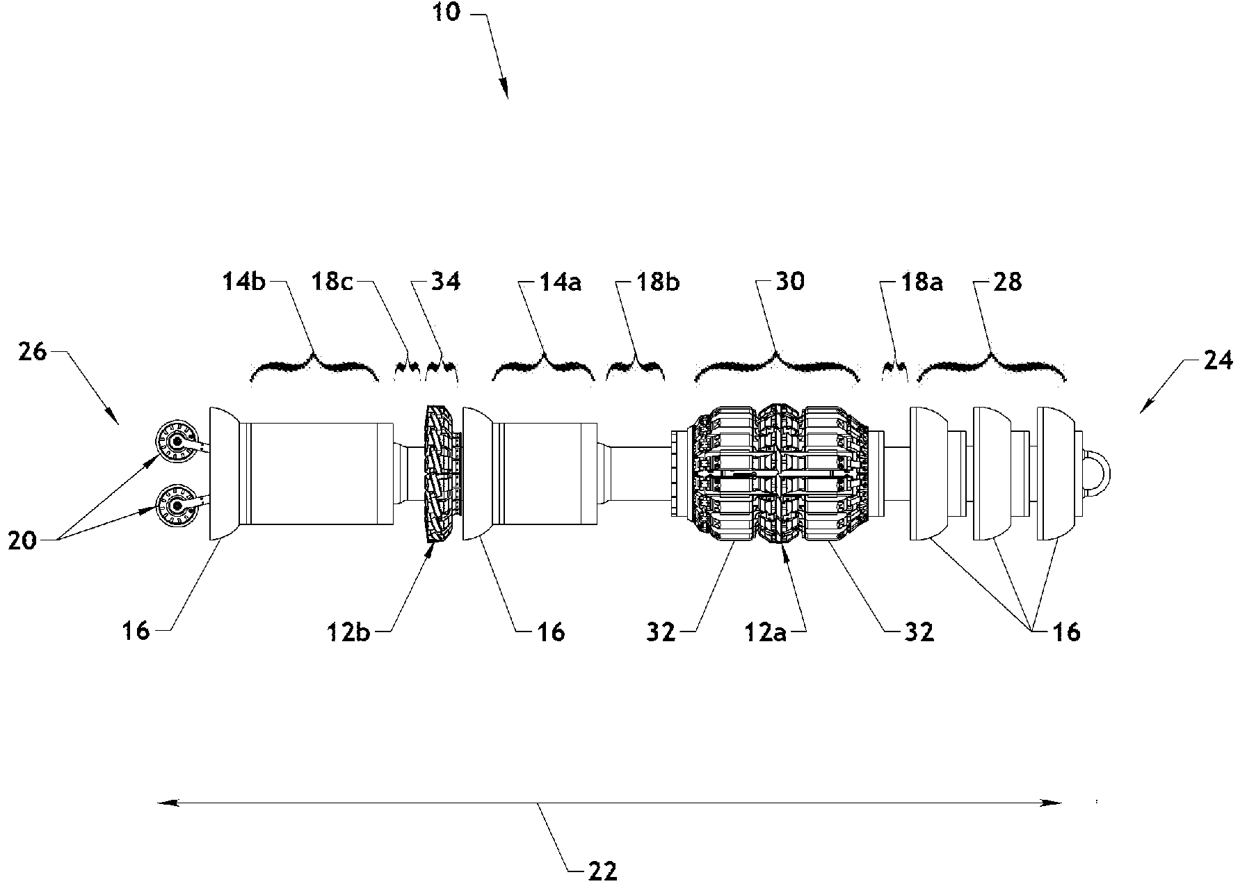
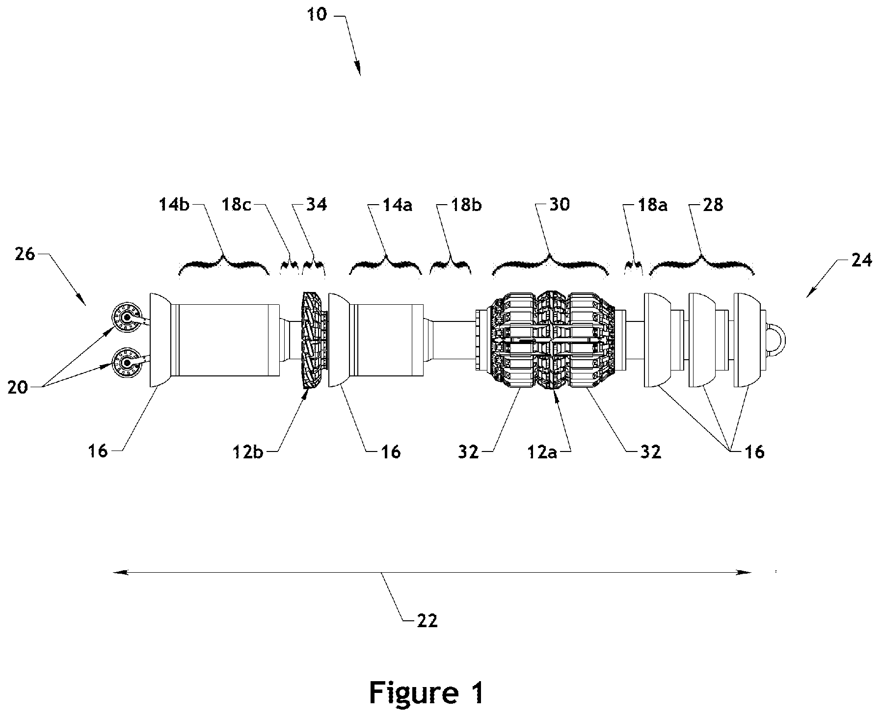
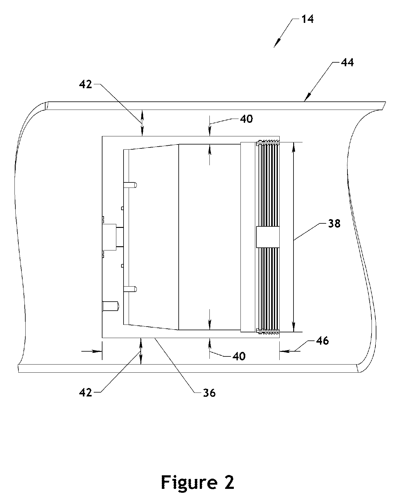
[0031]Referring to FIG. 1, an in-line inspection tool 10 in accordance with the present invention may comprise various components including inspection sensors 12, canisters 14, driving cups 16, couplers 18, position sensors 20, and the like. Canisters 14 may house equipment such as one or more processors, memory devices, and bat...


PUM


Abstract

An in-line inspection tool comprising a sensor suite, a processor processing the signal generated by at least one sensor of the sensor suite, and a canister housing the processor is disclosed. The canister may comprise a canister body formed as a hollow cylinder extending along a central axis from a first end to a second end. The canister may further comprise a canister lid inserted within the first end of the canister body. An alignment mechanism may prevent rotation of the canister lid with respect to the canister body about the central axis. A retaining ring may threadedly engage the first end of the canister body to maintain the canister lid within the first end of the canister body.

Description

RELATED APPLICATIONS[0001]This application (1) claims the benefit of co-pending U.S. Provisional Patent Application Ser. No. 61 / 065,456 filed Feb. 11, 2008 and (2) is a continuation-in-part of co-pending U.S. patent application Ser. No. 12 / 200,934 filed Aug. 29, 2008.BACKGROUND[0002]1. Field of the Invention[0003]This invention relates to pipeline inspection tools, and more particularly to apparatus and methods for a canister for use within an in-line inspection tool.[0004]2. Background of the Invention[0005]Oil, petroleum products, natural gas, hazardous liquids, and the like are often transported using pipelines. The majority of these pipelines are constructed from steel pipe. Once installed, a pipeline will inevitably corrode or otherwise degrade. Proper pipeline management requires identification, monitoring, and repair of defects and vulnerabilities of the pipeline. For example, information collected about the condition of a pipeline may be used to determine safe operating pres...

Claims


Application Information

Patent Timeline
Patent Type & Authority Applications(United States)
IPC IPC(8): G01M19/00G01M99/00
CPCG01M3/005
Inventor HOYT, PHILIP M.FOX, ARTHUR K.
Owner PURETECH VENTURES
Why Eureka
Try Eureka