Method Of Removing Solids From Bitumen Froth

a bitumen froth and solid removal technology, applied in the petroleum industry, liquid hydrocarbon mixture production, etc., can solve the problems of inability to achieve real-time monitoring and control of the settling process in paraffinic froth treatment, time and labor-intensive procedures, and inability to lend themselves

Inactive Publication Date: 2009-08-13
HOMMEMA SCOTT E
View PDF85 Cites 15 Cited by
  • Summary
  • Abstract
  • Description
  • Claims
  • Application Information

AI Technical Summary

Problems solved by technology

These procedures are time and labor-intensive and generally do not lend themselves to automatic on-stream implementation or permit timely adjustments to the operating conditions.
Therefore, direct, real-time monitoring and control of the settling process in paraffinic froth treatment is not achieved with existing instrumentation and techniques.
Further, such an approach is undesirable because it requires long periods of time (e.g., hours) to respond to changes in the feed composition and changes in the level of the vessel may relate to parameters other than product quality and particle size.
Further, the method of the '623 reference is undesirable because it requires the development of a database of “calibration models,” which would require significant time and effort.
The Leschonski reference does not disclose the use of on-line, real-time optical measurements.
These analyses take hours to complete, so the data are not available to make real-time process control decisions.
Furthermore, this type of data only reveals whether or not product specifications were being met at the time of sampling.
The results do not provide much information regarding the gravity-based settling process nor do they indicate how close to the edge of an operating envelope one may be operating.

Method used


Image

  • Method Of Removing Solids From Bitumen Froth
  • Method Of Removing Solids From Bitumen Froth
  • Method Of Removing Solids From Bitumen Froth

Examples


example 1

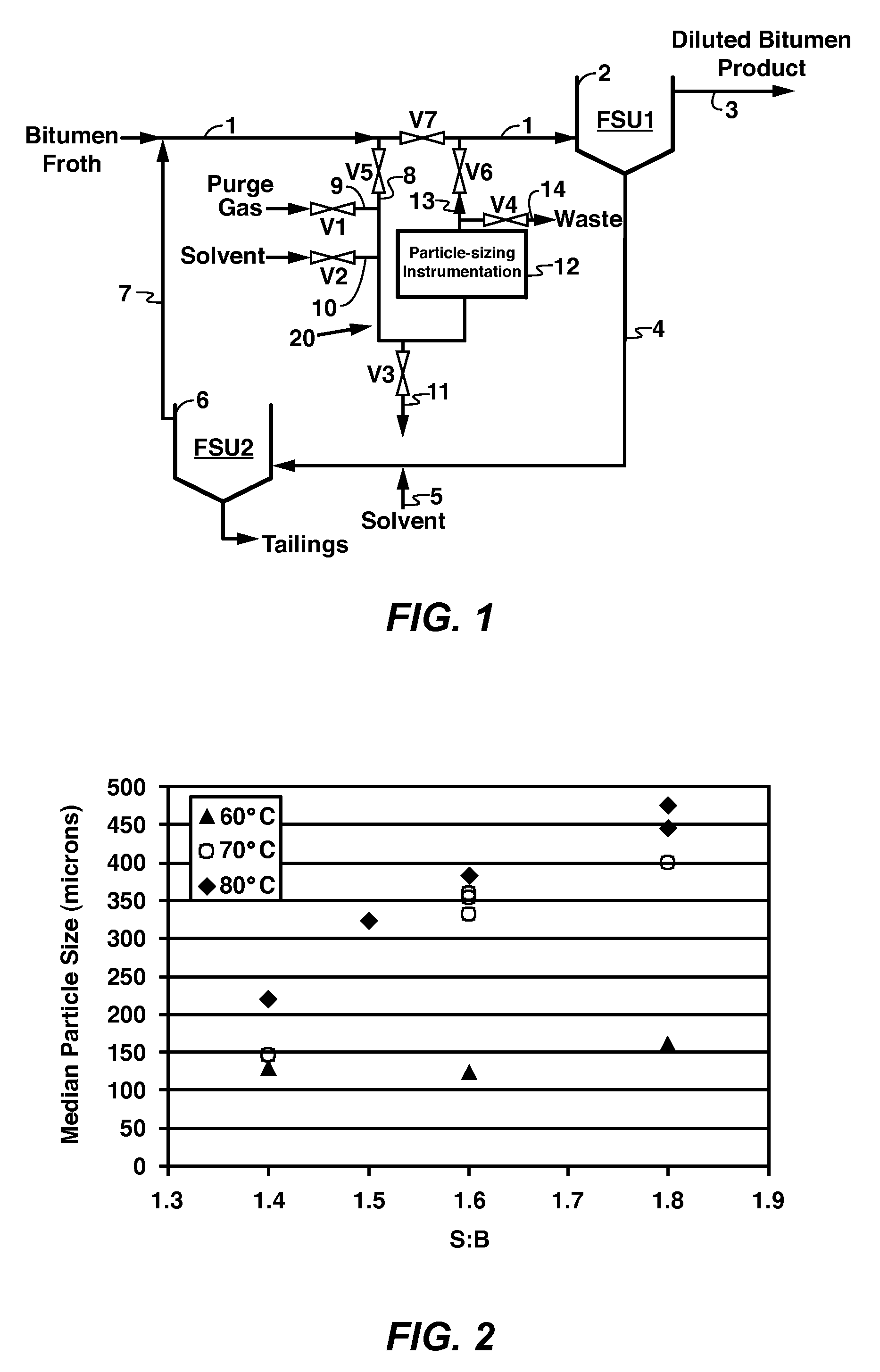
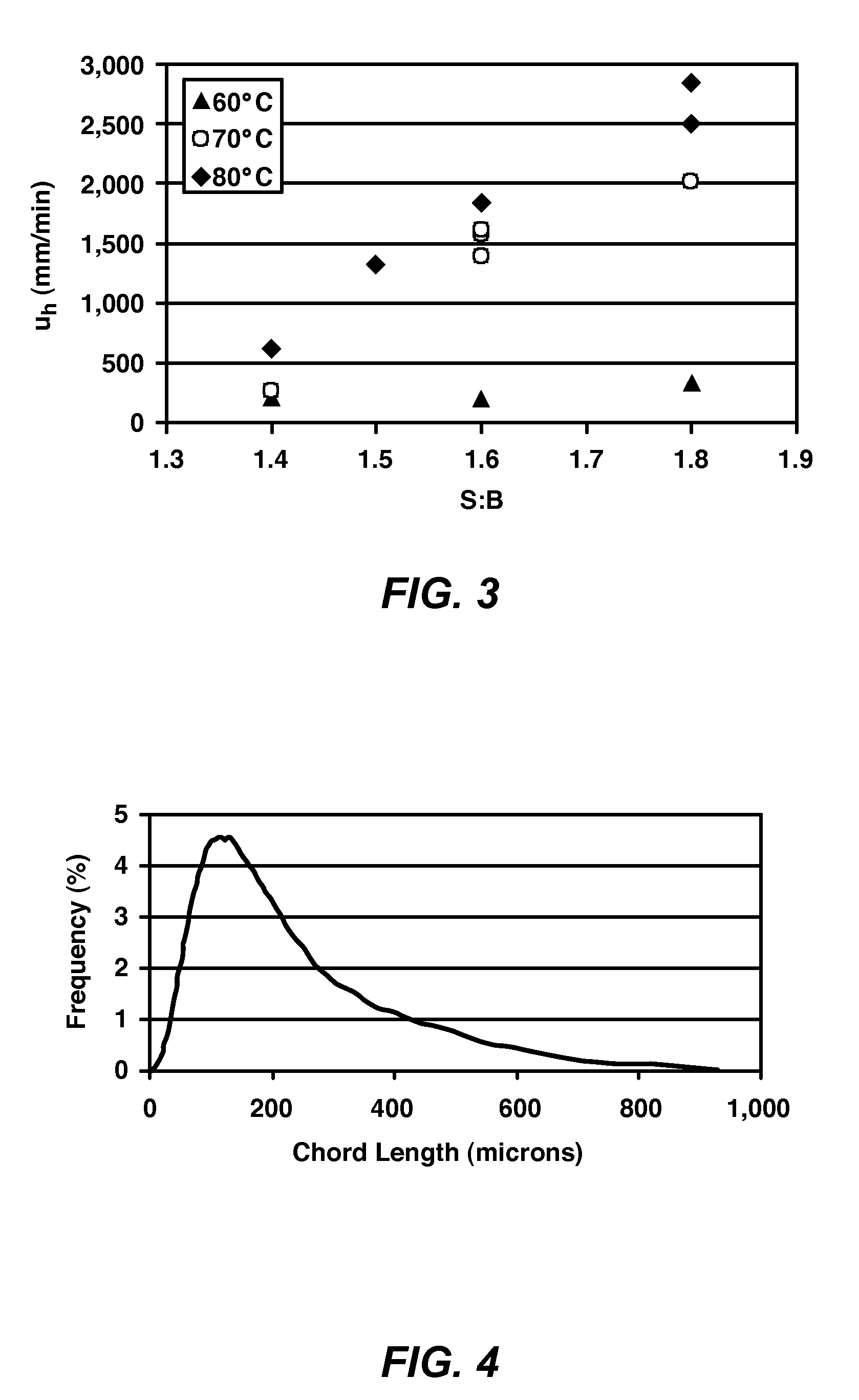
[0051]This example 1 demonstrates variation in median particle size and hindered settling rate with changes in the solvent-to-bitumen ratio (hereinafter “S:B”) or temperature.

[0052]A parametric study was conducted in a 15 barrel per day (bitumen froth feed) pilot plant. Commercial bitumen froth obtained from Syncrude Canada Ltd. (nominally 60 wt % bitumen, 30 wt % water, 10 wt % mineral solids) was fed to a paraffinic froth treatment (“PFT”) process using a 60 / 40 vol % blend of iso / normal pentane as the paraffinic solvent.

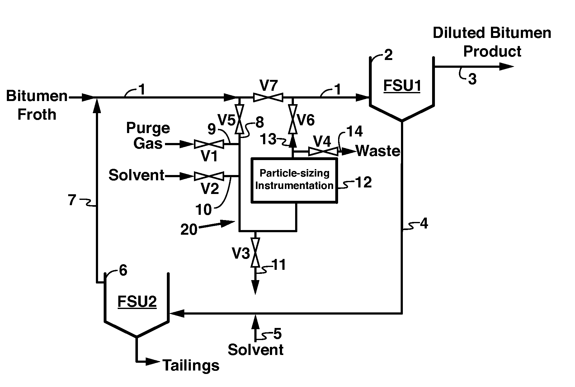
[0053]PSI 12 (Lasentec FBRM by Mettler-Toledo) was placed in the feed piping to the first froth settling unit (FSU1) 2 as indicated in FIG. 1. This location is downstream of the point where solvent in stream 7 is introduced into the bitumen froth feed 1 but upstream of the FSU12. A dichlorodimethylsilane coating had been applied to the probe's window (using the process described in paragraph [0030] prior to insertion into the process piping to reduce the propensity...

example 2

[0058]This Example demonstrates the characteristic PSD associated with a fouled or obscured optical window.

[0059]A parametric study was conducted as in Example 1 including PSI placement, probe window coating and start-up procedure.

[0060]When the process fluid was first introduced past a clean PSI, PSDs similar to that shown in FIG. 4 were observed. In this case 3,736 chords / second were recorded by the probe. However, after 140 min of operation, a PSD like that shown in FIG. 5 was observed. The high particle count, 15,831 chords / s, and noisy distribution are indicative of a fouled probe. The probe was removed from the instrumentation loop and examined. A thick, sticky, black film was observed, confirming that the probe surface was obscured.

example 3

[0061]This Example demonstrates the effectiveness of the described cleaning process.

[0062]In this test, the PSI (Lasentec FBRM by Mettler-Toledo) was placed in the feed piping 1 to the first-stage settling vessel (FSU1) 2 as indicated in FIG. 1. As before, this location is downstream of the point where solvent in stream 7 is introduced into the bitumen froth feed but upstream of the FSU12. A dichlorodimethylsilane coating had been applied to the probe's window as for Example 1 prior to insertion into the process piping to reduce the propensity for fouling. Initial baseline readings of the PSI indicated less than 100 counts. Process fluid was introduced into the PSI piping using the preferred start-up procedure described above for Example 1.

[0063]CLD's similar to that shown in FIG. 6 were observed for the first approximately 90 minutes of operation (curve 20). After 90 minutes, however, a CLD characteristic of a fouled probe was observed (curve 21). At 99 minutes, the following clean...


PUM

PropertyMeasurementUnit
temperatureaaaaaaaaaa
pressureaaaaaaaaaa
vol. %aaaaaaaaaa

Abstract

A paraffinic solvent, gravity-based process is disclosed for removing solids content from bitumen froth streams comprising the steps of placing particle-sizing instrumentation in a bitumen froth inlet stream to a gravity settling vessel subsequent to the addition of paraffinic solvent. The addition of solvent forming aggregates. A representative particle size distribution of entrained aggregates is measured with the particle-sizing instrumentation. The settling rate of the aggregates from the particle size distribution is determined mathematically. Operating data is collected while repeating one or more times the foregoing process steps and while changing one or more process conditions of the gravity-based process. A set of operating conditions are then established based upon particle size and settling rate from the generated data. The paraffinic solvent, gravity-based process is operated by adjusting process conditions to optimize the settling rate of the aggregates based upon the established set of operating conditions.

Description

CROSS REFERENCE TO RELATED APPLICATIONS[0001]This application claims the benefit of U.S. Provisional Application No. 61 / 066,183, filed Feb. 19, 2008. This application is related to U.S. Provisional Application No. 61 / 065,371, entitled “Upgrading Bitumen in a Paraffinic Froth Treatment Process”, filed Feb. 11, 2008.FIELD OF INVENTION[0002]This invention relates generally to the removal of asphaltenes, other solids and water from bitumen froth that is generated in the processing of mined oil sands in producing hydrocarbon feed stocks suitable for refining.BACKGROUND OF THE INVENTION[0003]In the processing of mined oil sands, bitumen froth is generated through a combination of water / aqueous extraction, air flotation, and deaeration processes. Typically this deaerated bitumen froth takes the form of a bitumen emulsion containing approximately 60 wt % bitumen, 30 wt % water, and 10 wt % mineral solids (e.g., sand, clay).[0004]The contaminants, such as water (carrying corrosive metal chlo...

Claims


Application Information

Patent Timeline
Patent Type & Authority Applications(United States)
IPC IPC(8): C10G1/04
CPCC10G1/045
Inventor HOMMEMA, SCOTT E.
Owner HOMMEMA SCOTT E
Why Eureka
Try Eureka