Adhering Matter Inspection Equipment and Method for Inspecting Adhering Matter

a technology of adhering matter and equipment, applied in the field of adhering matter inspection equipment and a method for inspecting adhering matter, can solve the problems of high cost of inspection, long time required for inspection of one inspection object, and varied inspection conditions, so as to reduce contamination, reduce the frequency of inspection, and reduce the effect of variation of inspection conditions

Active Publication Date: 2009-08-13
HITACHI LTD
View PDF7 Cites 14 Cited by
  • Summary
  • Abstract
  • Description
  • Claims
  • Application Information

AI Technical Summary

Benefits of technology

[0012]With the constitution described above, the sample material adhered to the inspection object is peeled off by a wind blast of the compressed gas such as an air, and an amount of the sample material collected on the collection filter can be increased, as well as a variation of an inspection condition can be reduced.
[0013]In addition, by adding a self-cleaning function, which blows the compressed gas on an inner wall of the collection unit and/or on an arm holding the nozzle, to the adhering matter inspection equipment, an adhering matter inspection equipment which can discharge a remaining sample material and dusts from the

Problems solved by technology

However, there are issues that an inspection condition may be varied due to a variation of a wiping place and a wiping strength depending on each inspector.
In addition, a long time is needed for inspecting one inspection object because a whole baggage surface is wiped.
Due to the issues described above, a plurality of inspectors are required, thereby resulting in an expensive inspection.
In addition, since an inspector operates the probe, the inspector is required to have a highly-skilled technique for scanning a probe end along a surface of an inspection object, which may have a complex irregularity.
In the rotation brushes disclosed in the patent literatures 2 and 3, since only an outmost external surface of a baggage, which may have a complex irregularity such as a handle and a zipper, comes in contact with the rotation brushes, an

Method used


Image

  • Adhering Matter Inspection Equipment and Method for Inspecting Adhering Matter
  • Adhering Matter Inspection Equipment and Method for Inspecting Adhering Matter
  • Adhering Matter Inspection Equipment and Method for Inspecting Adhering Matter

Examples


first embodiment

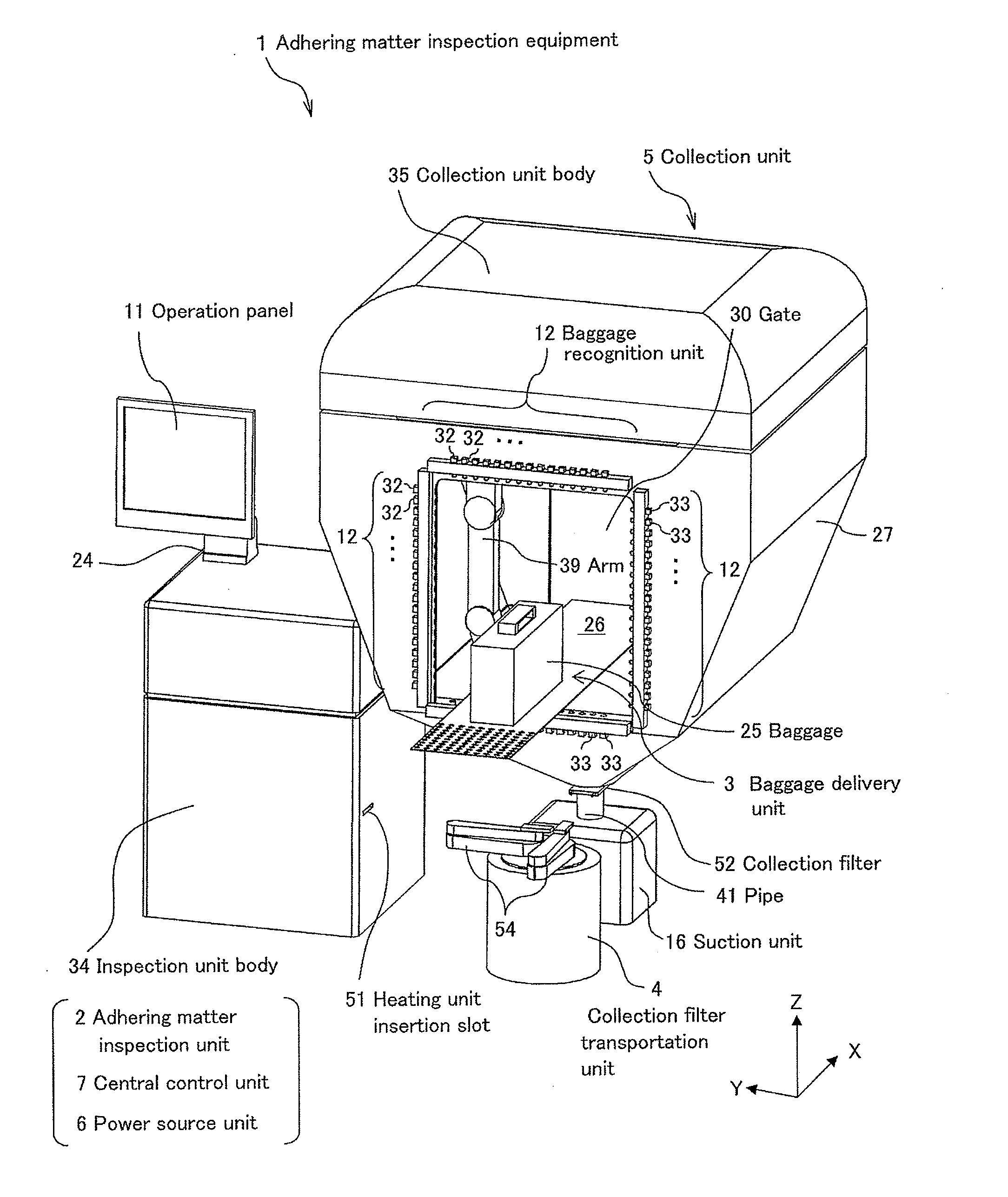
[0043]Hereinafter, an embodiment of the present invention will be explained in detail by referring to figures. In the following explanation of the embodiment, a dangerous material such as explosive fine particles or additives of explosives are exemplified as a sample material to be detected by an adhering matter inspection equipment, and a baggage of an examinee to which the dangerous material adheres is also exemplified as an inspection object. However, other than the explosive fine particles or the additives of explosives, an explosive material, a drug such as stimulant drugs, chemicals harmful to a human body, bacteria harmful to a human body, microorganisms such as virus, and the like which contain a sample material generally supposed to be harmful to a human body can be the inspection objects of the adhering matter inspection equipment according to the present invention, as well as a mail, a human body, and imported or exported goods. However, a sample material to be detected b...

second embodiment

[0156]FIG. 16 is a perspective view showing an outer shape of an adhering matter inspection equipment 1′ according to a second embodiment of the present invention. FIG. 17 includes a side view and a top view for explaining an adhering matter inspection equipment according to the second embodiment of the present invention. FIG. 17 (a) is a front view including a partial cross sectional view inside the sampling room 27 in an adhering matter collection unit 5′ of the adhering matter inspection equipment 1′ according to the second embodiment of the present invention.

[0157]In FIG. 17 (a), a cross section passes through an end face of the gate 30 of the sampling room 27 for a baggage, and the front view is a view as seen from a negative direction of the X-axis. Descriptions of each of units except for nozzle 75 (75a, 75b, 75c, 75d) and tube 76 (76a, 76b, 76c, 76d) are omitted. FIG. 17 (b) is a side view including a partial cross sectional view inside the sampling room 27 in the adhering m...

third embodiment

[0174]In addition, in the adhering matter inspection equipment 1 according to the first embodiment and the adhering matter inspection equipment 1′ according to the second embodiment described above, the explanations have been made assuming that the baggage 25 is the inspection object. However, a human body may be the inspection object too.

[0175]FIG. 19 is an illustration showing a side view and a top view for explaining a collection unit 5″ according to a third embodiment of an adhering matter inspection equipment 1″, in which a human body is assumed as the inspection object. FIG. 19 (a) is a top view of a sampling room 78 in the collection unit 5″ of the adhering matter inspection equipment 1″ according to the third embodiment of the present invention. FIG. 19 (b) is a side view including a partial cross section inside a sampling room 78 in the collection unit 5″ of the adhering matter inspection equipment 1″ according to the third embodiment of the present invention. In FIG. 19 (b...


PUM


Abstract

A technology for collecting a granular substance adhering to a baggage with high rate without touching the substance and inspecting whether a dangerous or specific sample material is adhered to the baggage. A method for simplifying or automating such an inspection is also provided. An adhering matter inspection equipment (1) is characterized in that the equipment comprises a collecting section (5) for collecting a sample material peeled off from an inspection object (25) whereupon the sample material is adhered by blowing compression gas through a capturing filter (52), and an inspecting section (2) for analyzing the sample material captured by the capturing filter (52), and further characterized in that the inspection equipment comprises a section (3) for delivering a baggage to the inspecting section (2), and a carrying section (4) for carrying the capturing filter (52) from the capturing section (5) to the inspecting section (2).

Description

TECHNICAL FIELD[0001]This invention generally relates to a technology for inspecting a substance (sample material) adhered to an inspection object, and particularly to an adhering matter inspection equipment and a method for inspecting an adhering matter, for mainly inspecting a substance adhered to a baggage and a human body.BACKGROUND ART[0002]Technologies for inspecting a baggage whether or not dangerous materials such as explosives and drugs are hidden in the baggage at a boarding gate of an airport and a port are disclosed, for example, in a patent literature 1, patent literature 2, patent literature 3, and patent literature 4. All technologies disclosed in the patent literatures 1 to 4 are technologies for estimating a substance included in a baggage by inspecting a sample material (granular substance) adhered to a surface of the baggage.[0003]In the patent literature 1, a transfer technology for transferring a sample material which adheres to a baggage surface to a wiping mat...

Claims


Application Information

Patent Timeline
IPC IPC(8): B01D59/44G01N1/22H01J49/00
CPCG01N1/2205G01N2001/4027G01N2001/028G01N1/4022
Inventor KASHIMA, HIDEOTAKADA, YASUAKIWAKI, IZUMI
Owner HITACHI LTD
Why Eureka
Try Eureka