Switching controller having programmable feedback circuit for power converters

a technology of power converters and feedback circuits, which is applied in the direction of electric variable regulation, process and machine control, instruments, etc., can solve the problems of low conversion efficiency, redundant power consumption is wasted on the switching loss of power switch b, power loss of rectifier, etc., to improve efficiency, reduce conversion loss, and increase cost

Active Publication Date: 2009-08-13
SEMICON COMPONENTS IND LLC
View PDF6 Cites 12 Cited by
  • Summary
  • Abstract
  • Description
  • Claims
  • Application Information

AI Technical Summary

Benefits of technology

[0017]The present invention is further directed to reduction of conversion loss and improvement of the efficiency without adding circuitries and increasing cost on light-load conditions.

Problems solved by technology

This lowers the conversion efficiency because a sufficient level of the output voltage VO on the light-load condition would be only 300 VDC, for example.
Redundant power consumption is therefore wasted on the switching loss of the power switch 10 and the power loss of the rectifier 30.
However, the determined level of the output voltage VO in the conventional art on the light-load condition is fixed because it is restricted by the reference voltages VL embedded in the switching controller 100a. This restricts the boost power converters to meet their practical power-saving requirements, for instance, to further reduce the determined level of the output voltage VO on the light-load condition from 300 VDC to 260 VDC.
The conventional art fails to externally programming its determined output voltage level required whenever needed.

Method used


Image

  • Switching controller having programmable feedback circuit for power converters
  • Switching controller having programmable feedback circuit for power converters
  • Switching controller having programmable feedback circuit for power converters

Examples


Embodiment Construction

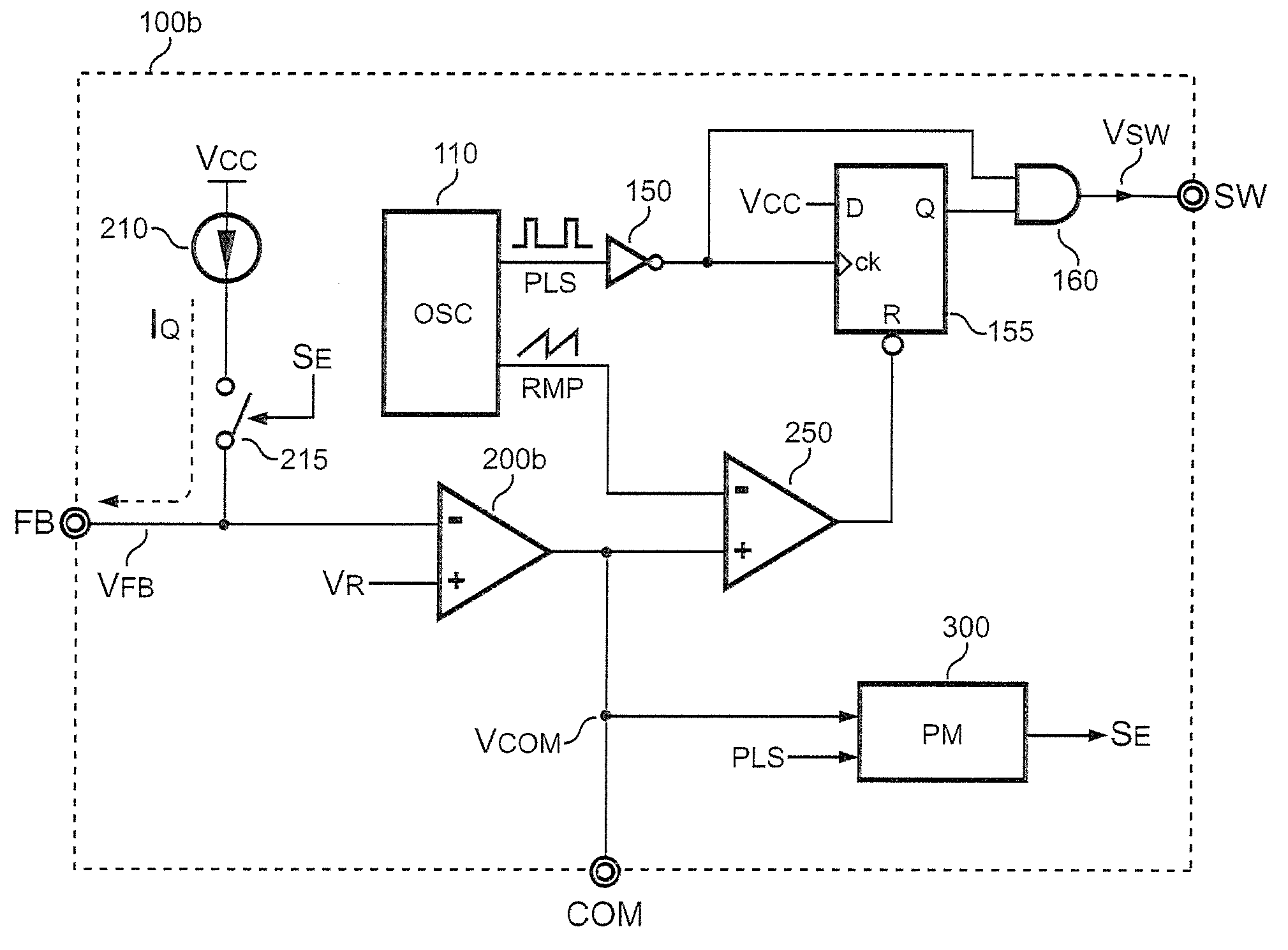
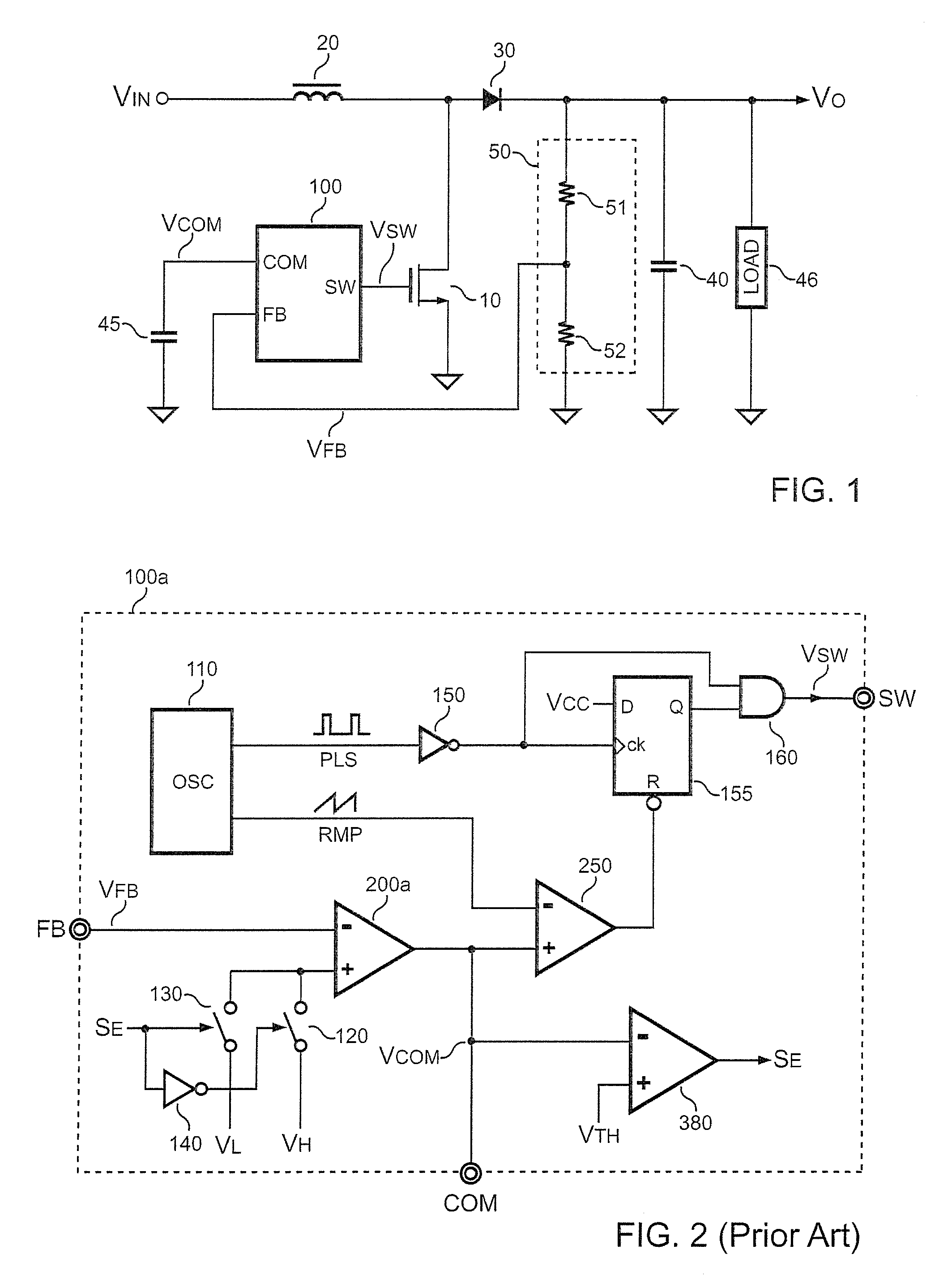
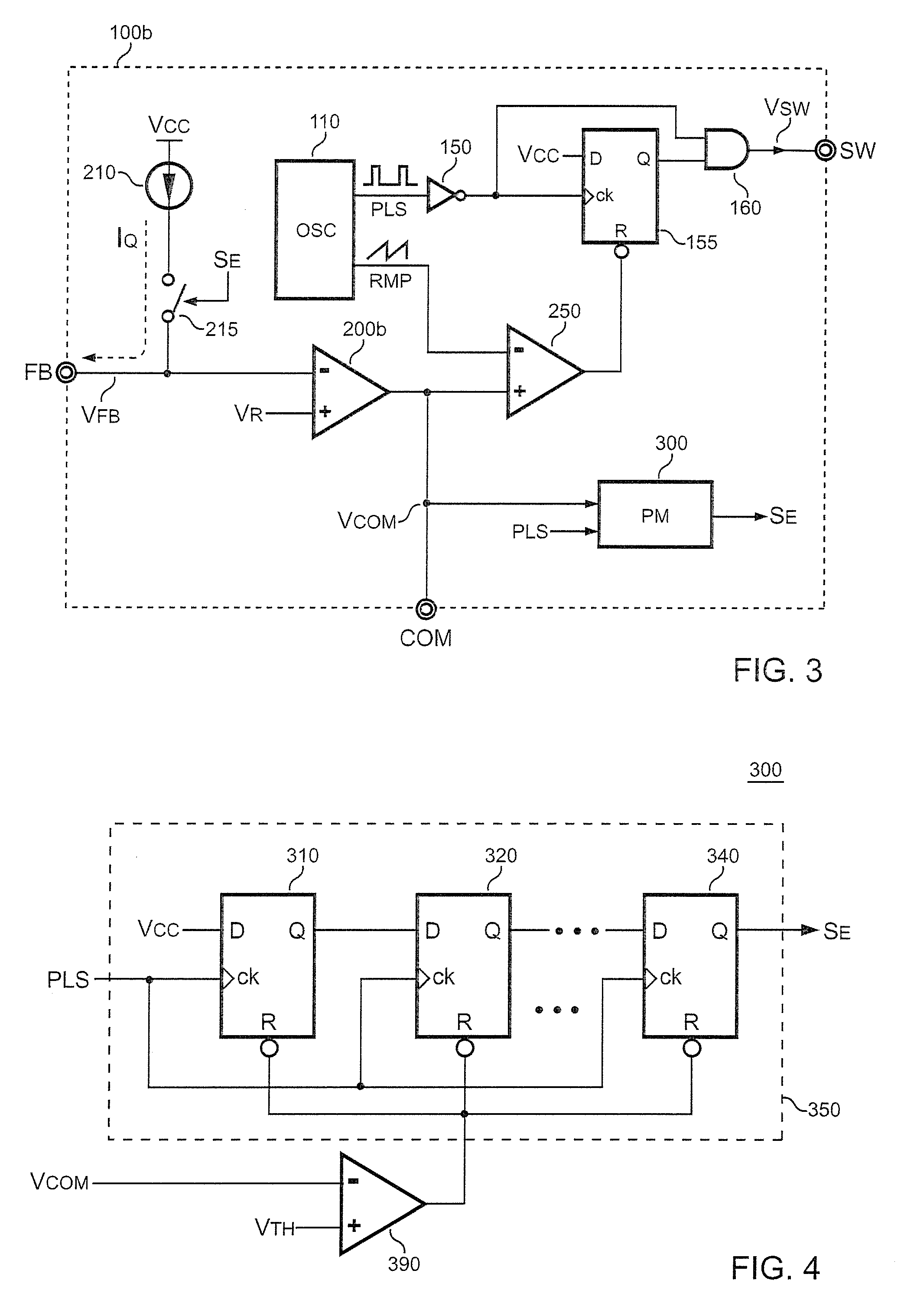
[0024]FIG. 3 shows a switching controller 100b of a boost power converter according to an embodiment of the present invention. The switching controller 100b comprises a switching-control circuit including the oscillator 110, the inverter 150, the flip-flop 155, the AND gate 160 and the comparator 250. The operation of the switching-control circuit in FIG. 3 is already explained in FIG. 2 and will be omitted herein.

[0025]As shown in FIG. 3, a feedback terminal FB of the switching controller 100b is connected to a negative terminal of an error amplifier 200b. A positive terminal of the error amplifier 200b is supplied with a feedback threshold VR. The error amplifier 200b receives an output signal VFB and the feedback threshold VR to generate a feedback signal VCOM. The switching controller 100b further comprises a programmable feedback circuit. The programmable feedback circuit comprises the error amplifier 200b, a current source 210, a switch 215, and a power management circuit 300....


PUM


Abstract

A switching controller for a boost power converter includes a switching-control circuit and a programmable feedback circuit. The programmable feedback circuit is coupled to an output of the boost power converter via a voltage divider. The programmable feedback circuit includes a current source coupled to a switch. On a light-load condition, a power-saving signal turns on the switch. The switch will conduct a programming current supplied by the current source toward the voltage divider. Furthermore, the voltage divider is externally adjustable for programming a determined level of an output voltage of the boost power converter on the light-load condition. Additionally the present invention increases system design flexibility to meet practical power-saving requirements without adding circuitries and increasing cost.

Description

CROSS-REFERENCE TO RELATED APPLICATION[0001]This application claims the priority benefit of U.S. provisional application Ser. No. 61 / 065,201, filed on Feb. 7, 2008. The entirety of the above-mentioned patent application is hereby incorporated by reference herein and made a part of this specification.BACKGROUND OF THE INVENTION[0002]1. Field of the Invention[0003]The present invention relates to power converters, and more particularly, relates to a switching controller of power converters.[0004]2. Description of Related Art[0005]FIG. 1 schematically shows a circuit of a boost power converter. An input voltage VIN is supplied to an inductor 20. A rectifier 30 is connected between the inductor 20 and an output of the boost power converter to provide an output voltage VO. The output voltage VO is a boosted voltage which is higher than the input voltage VIN. The output voltage VO is used to power a load 46, for example, a PWM switching circuitry. A power switch 10 coupled to a joint of t...

Claims


Application Information

Patent Timeline
Patent Type & Authority Applications(United States)
IPC IPC(8): G05F1/10
CPCH02M3/156Y02B70/16H02M2001/0032H02M1/0032Y02B70/10
Inventor YANG, TA-YUNGHSU, CHIEN-TSUNCHEN, CHENG-SUNGCHIANG, TING-TA
Owner SEMICON COMPONENTS IND LLC
Why Eureka
Try Eureka