DC conversion apparatus

a conversion apparatus and dc technology, applied in the direction of electric variable regulation, process and machine control, instruments, etc., can solve the problems of increasing copper loss, substantially equalizing core loss and winding loss, and increasing so as to reduce the number of turns, increase copper loss, and increase the resistance value of secondary winding.

Active Publication Date: 2009-08-13
SANKEN ELECTRIC CO LTD
View PDF9 Cites 21 Cited by
  • Summary
  • Abstract
  • Description
  • Claims
  • Application Information

AI Technical Summary

Benefits of technology

[0025]However, increasing the number of turns of a secondary winding enlarges the resistance value of the secondary winding, to increase a copper loss. Accordingly, a standard transformer design for providing large output power increases the sectional area of a core of a transformer and reduces the number of turns on the secondary side, thereby substantially equalizing a core loss and a winding loss.
[0028]Namely, increasing the primary winding of the transformer T1 results in increasing the leakage inductance in proportion to a square of the number of turns. Power to be sent to the secondary side of the transformer T1 is proportional to a square root of Cri / Lr1 and an operating frequency is proportional to Cri×Lr1.
[0031]According to the present invention, a DC conversion apparatus that is small, inexpensive, and highly efficient can be provided.Means to Solve the Problems

Problems solved by technology

However, increasing the number of turns of a secondary winding enlarges the resistance value of the secondary winding, to increase a copper loss.
Accordingly, a standard transformer design for providing large output power increases the sectional area of a core of a transformer and reduces the number of turns on the secondary side, thereby substantially equalizing a core loss and a winding loss.
In this case, an output voltage will not finely be regulated if output power is large.
And when the reactor Lr1 forming a resonant circuit is a leakage inductance between the primary and secondary windings of the transformer T1, the below-mentioned problems will arise.

Method used


Image

  • DC conversion apparatus
  • DC conversion apparatus
  • DC conversion apparatus

Examples


embodiment 1

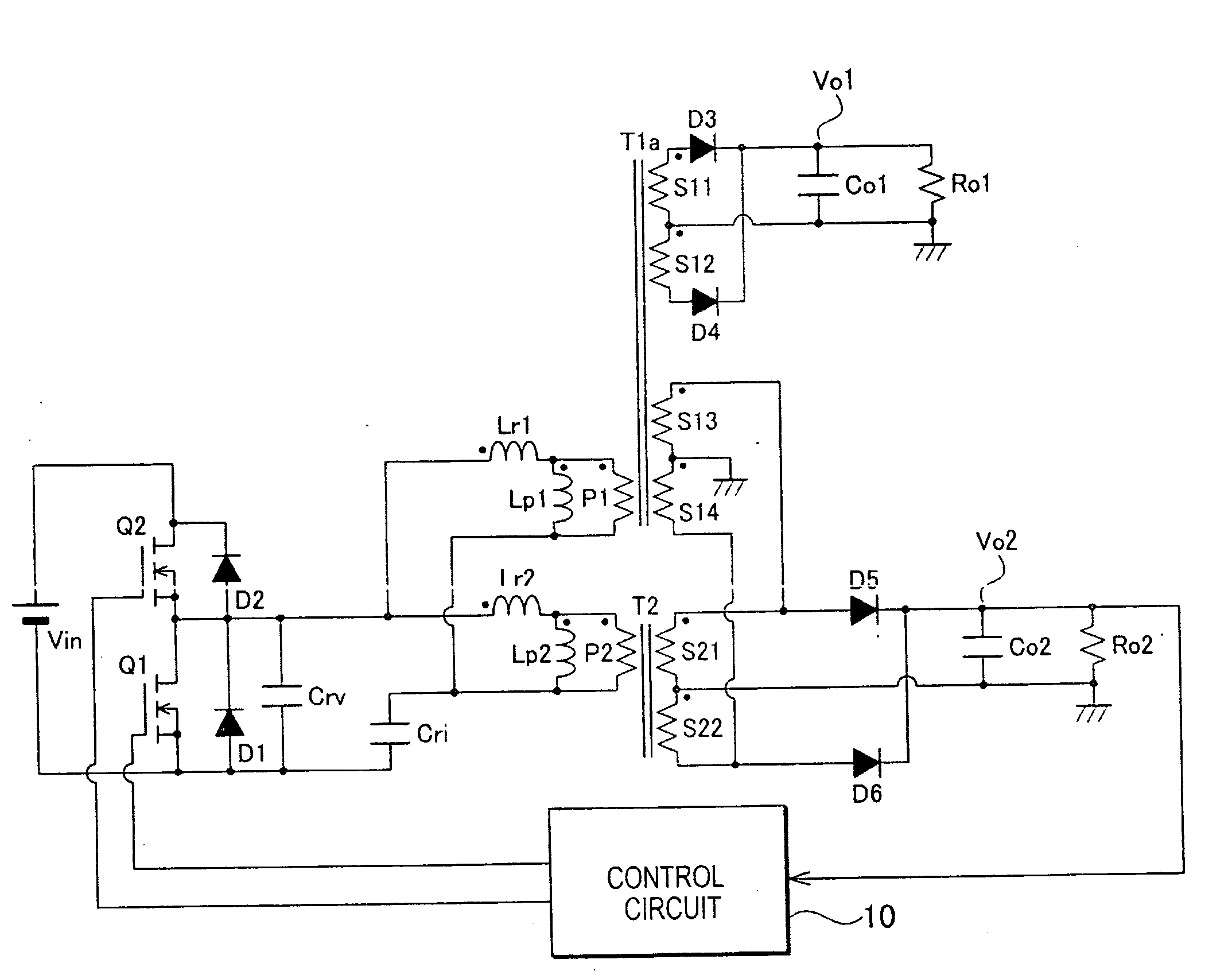
[0049]FIG. 5 is a circuit diagram illustrating a DC conversion apparatus according to Embodiment 1 of the present invention. The DC conversion apparatus of Embodiment 1 illustrated in FIG. 5 has a half-bridge circuit like the DC conversion apparatus as illustrated in FIG. 1.

[0050]A transformer (first transformer) T1a at least has a primary winding P1, first secondary windings S11 and S12, and second secondary Bindings S13 and S14. The first secondary windings S11 and S12 and the second secondary windings S13 and S14 are connected in series.

[0051]A transformer (second transformer) 12 at least has a primary winding P2 and first secondary windings S21 and S22. The first secondary windings S21 and S22 are connected in series.

[0052]The primary winding P1 of the transformer T1a and a reactor (first reactor) Lr1 form a series circuit (first series circuit), and the primary winding P2 of the transformer f2 and a reactor (second reactor) Lr2 form a series circuit (second series circuit). The...

embodiment 2

[0079]FIG. 6 is a circuit diagram illustrating a DC conversion apparatus according to Embodiment 2 of the present invention. The present embodiment as illustrated in FIG. 6 employs a transformer t2a having secondary windings S23 and S24 in addition to the transformer T2 of the DC conversion apparatus of Embodiment 1 as illustrated in FIG. 5, to realize three outputs. The other parts of the configuration illustrated in FIG. 6 are the same as those of the DC conversion apparatus of Embodiment 1 as illustrated in FIG. 5, and therefore, the same parts are represented with the same reference marks.

[0080]A first end of the secondary winding S23 of the transformer T2a as depicted by a filled circle is connected to an anode of a diode D7. A second end of the secondary winding S23 of the transformer T2a and a first end (with a filled circle) of the secondary winding S24 of the transformer T2a are connected to a first end of a smoothing capacitor Co3. A second end of the secondary winding S24...

embodiment 3

[0082]FIG. 7 is a circuit diagram illustrating a DC conversion apparatus according to Embodiment 3 of the present invention. Compared with the DC conversion apparatus of Embodiment 1 illustrated in FIG. 5, the present embodiment as illustrated in FIG. 7 employs exclusive-use secondary windings S10 and S20 for coupling transformers T1b and T2b. The other parts of FIG. 7 are the same as those of the DC conversion apparatus of Embodiment 1 illustrated in FIG. 5, and therefore, the same parts are represented with the same reference marks.

[0083]The transformer T1b has the secondary winding (second secondary winding) S10 instead of the secondary windings S13 and S14 of the transformer T1a illustrated in FIG. 5. The transformer T2b has the secondary winding S20 (second secondary winding) in addition to the configuration of the transformer T2 illustrated in FIG. 5. A first end of the secondary winding S10 as depicted by a filled circle is connected to a first end (with a filled circle) of t...


PUM


Abstract

A DC conversion apparatus comprises a first transformer, a second transformer, a parallel circuit having series circuits connected in parallel, one of the series circuits including a reactor and a primary winding of the first transformer, the other series circuit including a reactor and a primary winding of the second transformer, a conversion circuit converting a DC voltage of a DC power source into an AC voltage and outputting it to the parallel circuit, a first rectifying-smoothing circuit rectifying and smoothing a first voltage generated by a first secondary windings of the first transformer into a first DC output, and a second rectifying-smoothing circuit rectifying and smoothing a second voltage generated by a first secondary windings of the second transformer into a second DC output that is different from the first voltage. The second secondary windings of the first transformer are connected in parallel with the first secondary windings of the second transformer.

Description

TECHNICAL FIELD[0001]The present invention relates to a DC conversion apparatus that is highly efficient, small, and inexpensive.BACKGROUND TECHNOLOGY[0002]FIG. 2 illustrates a circuit configuration of a multiple-output DC conversion apparatus according to a related art. FIG. 1 illustrates, as an example of a basic circuit to explain the multiple-output DC conversion apparatus, a circuit configuration of a single-output DC conversion apparatus disclosed in Japanese Unexamined Patent Application Publication No. 2003-319650.[0003]The DC conversion apparatus illustrated in FIG. 1 consists of a half-bridge circuit. Ends of a DC power source Mm are connected to a series circuit that includes a switching element Q1 made of a MOSFET and a switching element Q2 made of a MOSFET. A drain of the switching element Q2 is connected to a positive electrode of the DC power source Mm and a source of the switching element Q1 is connected to a negative electrode of the DC power source Vin.[0004]Betwee...

Claims


Application Information

Patent Timeline
Patent Type & Authority Applications(United States)
IPC IPC(8): H02M3/335
CPCH02M3/337Y02B70/1491H02M2001/0058Y02B70/10H02M1/0058H02M3/01H02M3/33571H02M3/33561H02M3/28
Inventor ASO, SHINJIKAMINAGA, YUKIHIRO
Owner SANKEN ELECTRIC CO LTD
Why Eureka
Try Eureka