Method and system for controlling link saturation of synchronous data across packet networks

a packet network and synchronous data technology, applied in the field of telecommunications network control, can solve the problems of reconstructed t1 experiencing underflow, t1 running, replacement data arriving too late to be forwarded on the reconstructed telecommunications service, etc., and achieve the effect of lessening the potential for overload

Inactive Publication Date: 2009-08-13
ERICSSON WIFI
View PDF12 Cites 16 Cited by
  • Summary
  • Abstract
  • Description
  • Claims
  • Application Information

AI Technical Summary

Benefits of technology

[0007]The present invention relates to a method for controlling admissions of data packets across a packet network that delivers synchronous services. In doing so, the potential for overloading is lessened. The present invention also relates to a system for implementing the method. An exemplary embodiment of the method comprises the steps of establishing a communication route from a first provider edge (PE) element to a second provider edge element with at least one primary node (connected to each edge element to establish a link) and a plurality of secondary nodes disposed between the primary nodes of the edge elements. Each secondary node establishes a link with the next successive node and the links combining to establish the communication route. The embodiment also comprises the steps of: determining an amount of available network bandwidth for transmission of the data packets across each of the links of the communication route and determining whether to admit the data packets to each of the links of the communication route based on the determined amount of available network bandwidth across the respective link. The admission determination is capable of being performed at each of the respective secondary nodes.

Problems solved by technology

If the timing is incorrect, the reconstructed T1 may experience underflow (the data play out too quickly and the T1 runs out of data) or overflow (the data plays out too slowly and the T1 runs out of places to buffer the data and has to discard some of it).
The issue being that, if a retry is required, the replacement data will arrive too late to be forwarded on the reconstructed telecommunications service in a timely manner.
Low error rates are required by the telecommunications services because errors show up as audible effects, e.g., crackles, pops, hiss and silence gaps.
In the case of PWE, data lost transiting the PSN is replaced by silence or by replay of the data of the previous packet, each of which is an audible impairment of the service.
If the PSN is overloaded (a particularly acute problem when the PSN is composed of wireless links), lost packets will occur frequently.
This will degrade the service potentially to the point that it is unusable.
If many packets are lost, this analysis will be impossible or incorrect, resulting in timing errors that further degrade the service.

Method used


Image

  • Method and system for controlling link  saturation of synchronous data across packet networks
  • Method and system for controlling link  saturation of synchronous data across packet networks
  • Method and system for controlling link  saturation of synchronous data across packet networks

Examples


example 1

[0070]An exemplary application is T1 transport over the CESoPSN version of PWE. A T1 consists of 8000 frames / second of 193 bits for a net bit rate of 1.544 Mbps. The 193 bits consist of 1 framing bit plus 24 Digital Signal Zeroes (DS0s) of 8 bits each. In CESoPSN, the system does not transport the entire T1, instead, the system transports the (operator) selected DS0s.

[0071]In order to create data packets, selected DS9s are taken from some number of T1 frames. The more frames there are, the larger the packet is and the longer the delay introduced by its creation is. The more DS9s that are selected, the larger the packet is, however, there is no delay effect associated therewith. Larger packets are more efficient to transport because the packet header is 62 bytes long and must be included in each packet.

[0072]Set A: With 32 frames / packet and all 24 DS9s selected, packet size is 62 header bytes plus 32 frames multiplied by 24 bytes / frame, which equals 830 bytes. A packet rate of 8000 f...

example 2

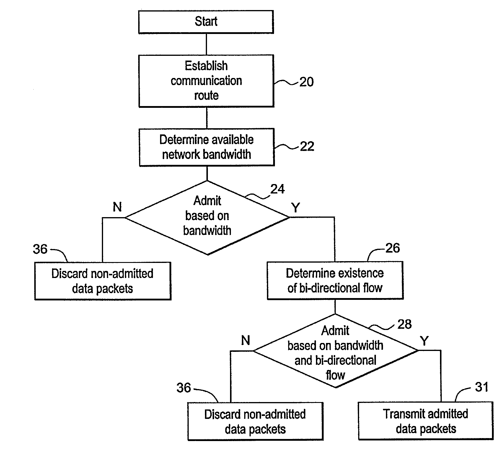
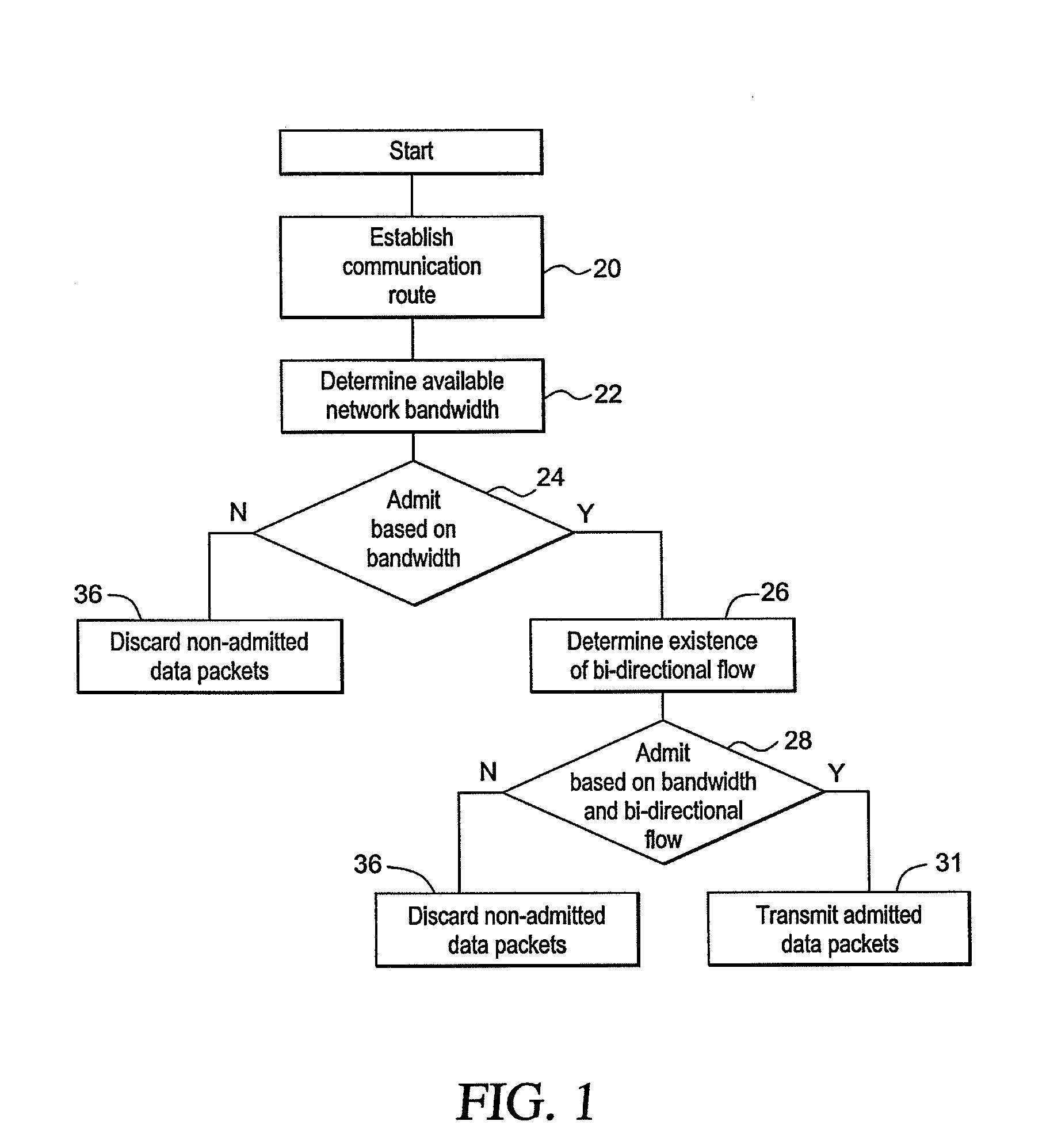
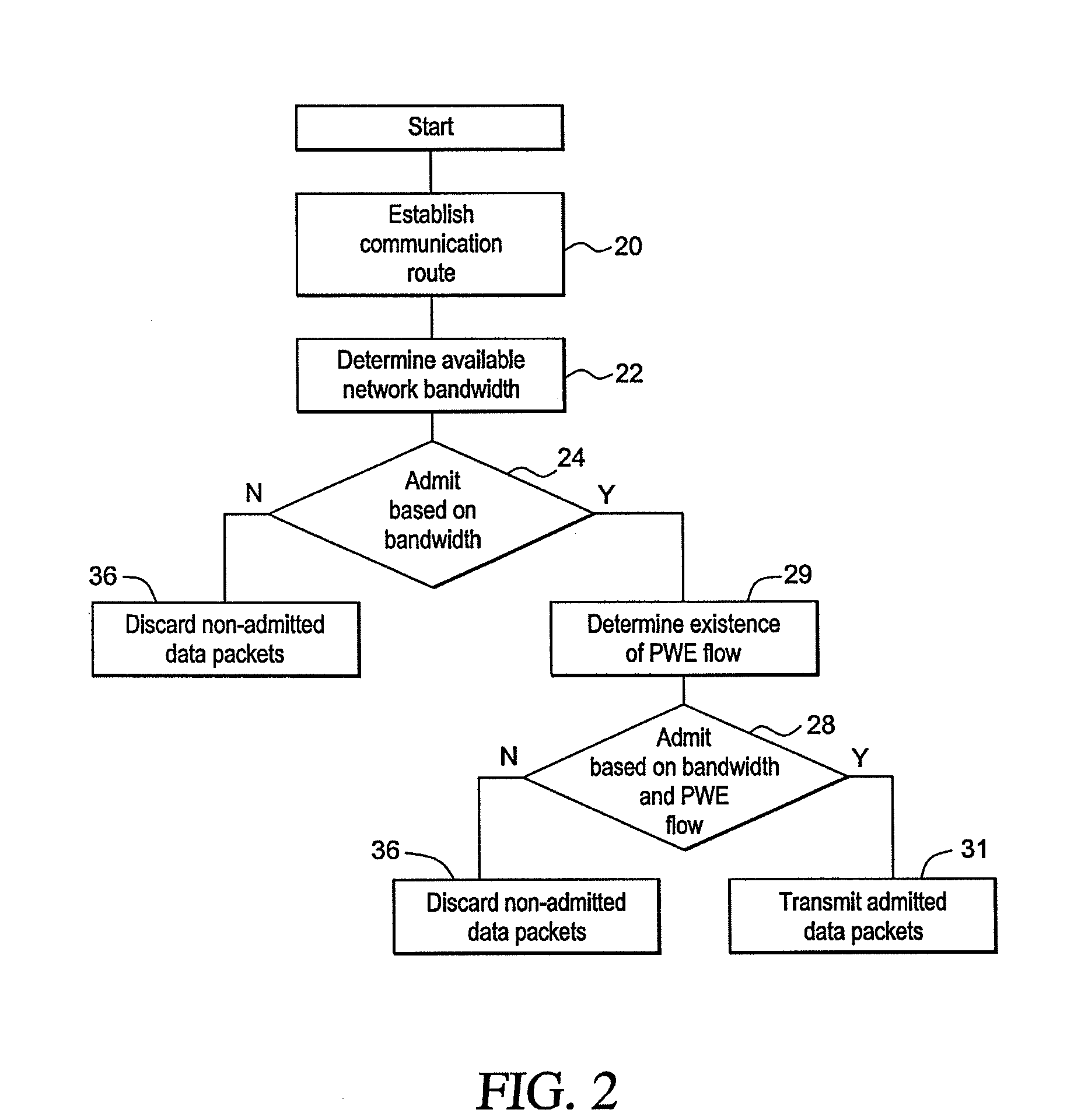
[0078]FIG. 6 shows an exemplary T1 PWE connection set-up procedure. In FIG. 6, timing flows from top to bottom. A first event, labeled “context admin up,” indicates that the operator activates the PE element of a PWE traffic flow. This triggers an Address Resolution Protocol (ARP) message to determine if the destination is reachable. If it is not, ARPs will be repeated indefinitely until a response is received or the operator deactivates the flow. When the ARP request reaches the RE element, a response is generated and returned. At this point, the edge elements know they can communicate with one another, but they do not know whether the required network bandwidth is available.

[0079]Upon receiving the ARP response, the transmitting PE element begins generating traffic. This traffic is identified at the RM, which determines the required capacity and makes two decisions: is there capacity, and is there bi-directional PWE flow. In this case, there is capacity but no return flow. The RM ...

example 3

[0083]FIG. 7 shows an exemplary T1 PWE connection tear-down procedure. In FIG. 7, timing flows from top to bottom. The halting of one direction of flow is shown. The RMs detect the interruption and start timers. If the traffic does not resume, the timers expire and the flow is recognized as uni-directional. The first RM blocks the remaining direction of traffic flow. Both RMs release the capacity reserved for this flow and make it available for a new flow or possible re-establishment of the current flow.

[0084]The following non-limiting examples demonstrate the ability of the invention to handle more complex cases, e.g., redundant network paths, multiple redundant network paths, and multiple provider edge nodes. In these types of complex cases, if failures collapse too much traffic onto a single link, prior systems would randomly discard traffic thereby rendering all the PWE useless because too many dropped packets results in too much noise and an inability to recover appropriate tim...


PUM


Abstract

A method for controlling admissions of data packets across a packet network comprising the steps of establishing a communication route along a plurality of interconnected secondary nodes, determining an amount of available network and determining whether to admit the data packets to the communication route based on the determined amount of available network bandwidth. Also disclosed is a system for implementing the method comprising a first provider edge element, a second provider edge element, a plurality of interconnected secondary nodes disposed between the edge elements. Each of the secondary nodes comprises at least one first detection device for determining an amount of available network bandwidth and at least one admission device in communication with the respective first detection device for determining whether to admit the data packets to the communication route based on the determined amount of available network bandwidth.

Description

BACKGROUND OF THE INVENTION[0001]1. Field of the Invention[0002]The present invention relates to telecommunications network control. More specifically, the present invention relates to a method, and an accompanying system, for controlling admissions of data packets across a packet network that delivers synchronous services.[0003]2. Background Information[0004]Pseudo wire emulation (PWE) is a mechanism that emulates the essential attributes of a telecommunications service over a packet switched network (PSN). PWE is intended to provide only the minimum necessary functionality to emulate a wire with the required degree of faithfulness for the given service definition. The telecommunication service offered to the customer is delivered by a particular attachment circuit (AC). The service provider edge (PE) equipment translates this AC into a packet based service that can be tunneled across a PSN using the PWE protocol. The tunnel between two PE end-points is referred to as a pseudo-wire...

Claims


Application Information

Patent Timeline
Patent Type & Authority Applications(United States)
IPC IPC(8): H04L12/56H04L47/52H04L47/80H04L69/14
CPCH04L45/00H04L45/302H04L47/822H04L47/783H04L47/805H04L47/745
Inventor SOMMERVILLE, THOMAS RICHARDPLOTNIKOV, SERGEYDU, KAIZHEN
Owner ERICSSON WIFI
Why Eureka
Try Eureka