
Wavelength division multiplexing system, method and device for its residual dispersion compensation

a multiplexing system and wavelength division technology, applied in wavelength-division multiplex systems, optical transmission, multi-channel communication, etc., can solve the problems of difficult to precisely compensate the dispersion of other channels, reduce the tolerance of other channels, and avoid bit errors, etc., to achieve large tolerance and long distance. , the effect of large toleran

Active Publication Date: 2009-08-13
ZTE CORP
View PDF11 Cites 12 Cited by
  • Summary
  • Abstract
  • Description
  • Claims
  • Application Information

AI Technical Summary

Benefits of technology

[0015]The object of the present invention is to provide a wavelength division multiplexing system and method and device for its residual dispersion compensation, which uses a tunable dispersion compensator to compensate the residual dispersion of the channel layer compensated by a fiber dispersion compensation module of multiplexing section of wavelength division multiplexing optical transmission system to optimize residual dispersion of each channel and solve the problem of deterioration of transmission performance caused by residual dispersion in long-distance optical transmission system.
[0035]The method and device for adjusting residual dispersion compensation of wavelength division multiplexing system of the present invention achieves the dynamic control of residual dispersion of wavelength division multiplexing optical transmission system, effectively solves the technical problem of residual dispersion accumulation of wavelength division multiplexing optical transmission system with large tolerance and long distance and realizes super long distance transmission of wavelength division multiplexing system with large tolerance by detecting performance parameter of the receiving terminal optical signal and dynamically feeding back and regulating the tunable dispersion compensator.

Problems solved by technology

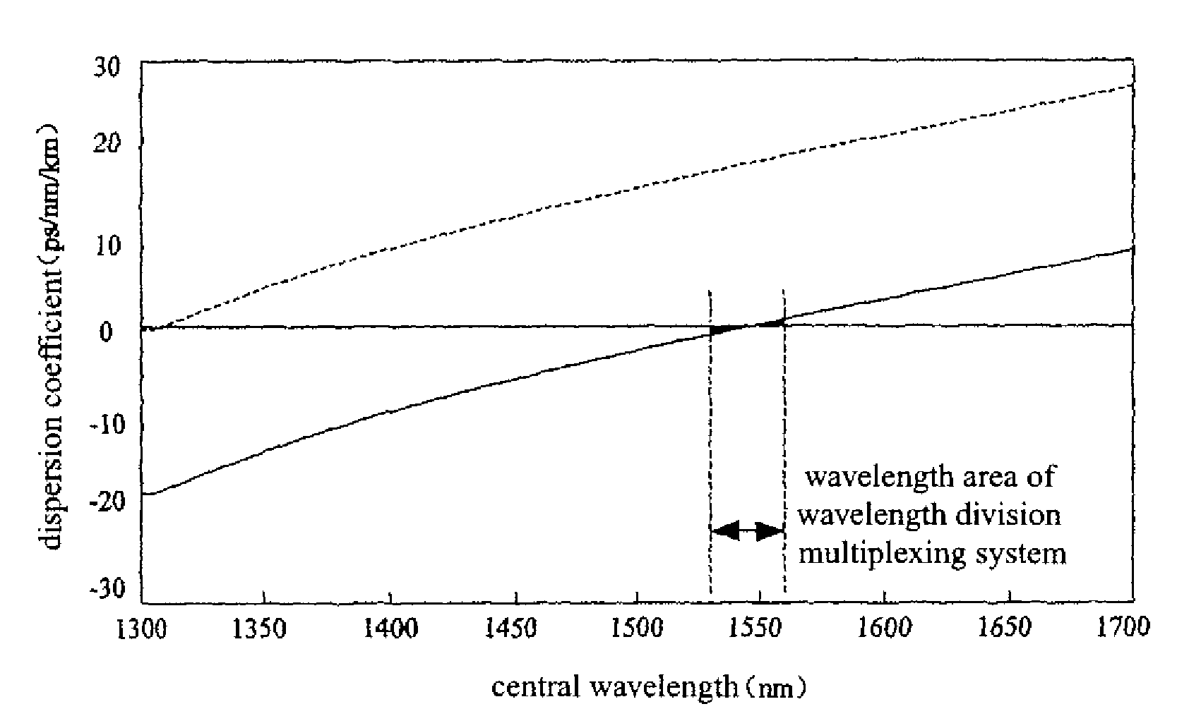
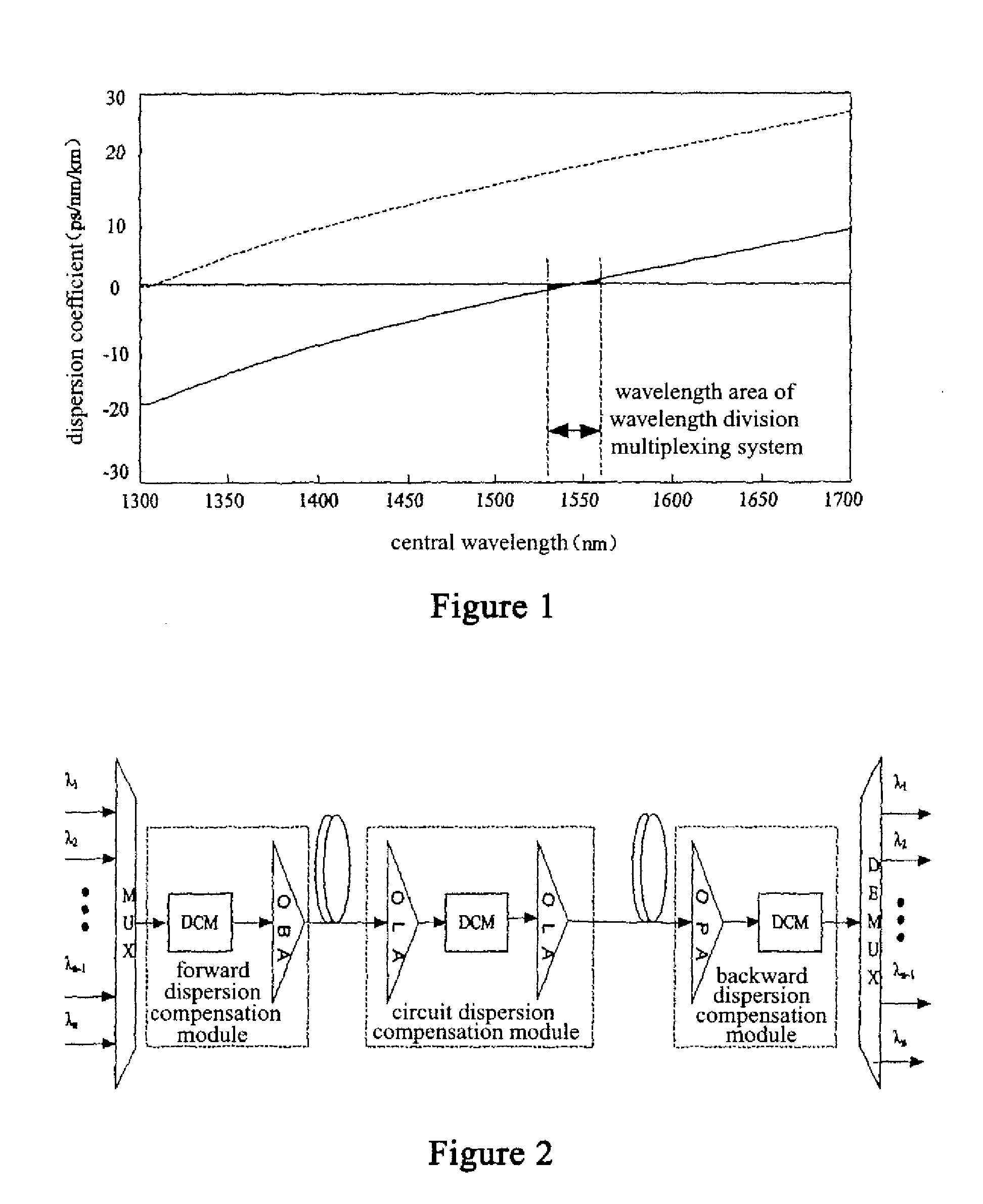
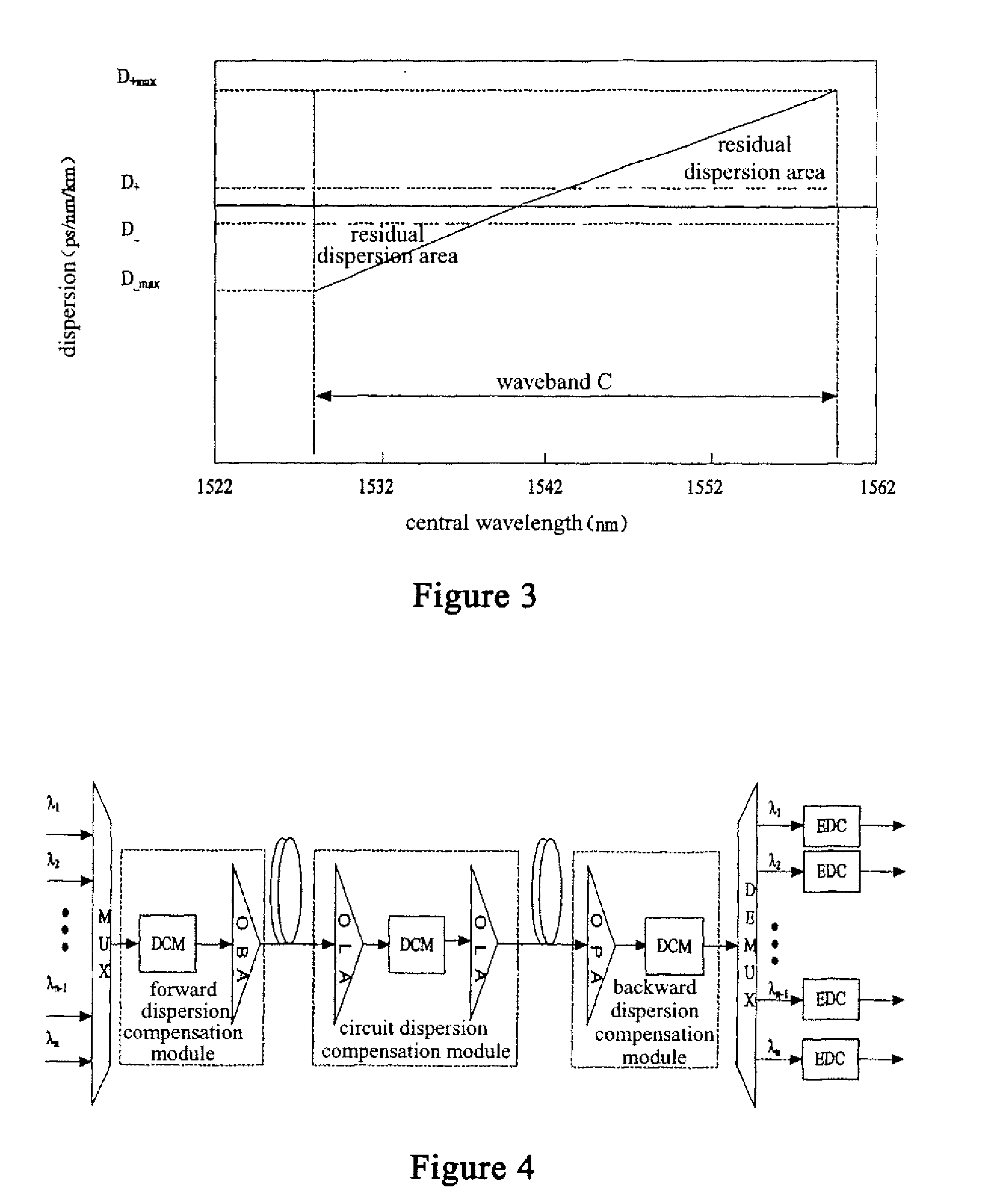
However, as the relative dispersion slopes between common fiber and dispersion compensation module are not always the same, in the condition of large amount of channels and long transmission distance, even if residual dispersion of a channel of a certain wavelength is completely optimized to have the lowest bit error rate, residual dispersion of other channels (especially edge wavelength channels) may also be large, which can hardly avoid bit errors after transmission. FIG. 3 is a schematic view showing residual dispersion of wavelength division multiplexing optical transmission system, wherein D+ and D− are the ranges of dispersion tolerance permitted by receiver and D+max and D−max respectively represent the accumulating maximums of positive residual dispersion and negative residual dispersion.
Therefore, even if tunable dispersion compensator is used in the multiplexing section of wavelength division system, it is difficult to exactly compensate dispersion of all channels to optimum, so that over-compensation and lack-compensation of dispersion of each channel can hardly be avoided.
The accumulation of residual dispersion is very harmful to optical transmission system of super long distance and further even break down the optical transmission system.
However, the problem of the method above is: the dispersion compensation amount of electrical dispersion compensation device is fixed and very limited, which can reduce the effect brought by system residual dispersion in some degree, but can not essentially solve the problem of residual dispersion existing in the system and dynamically regulate dispersion compensation amount of each wavelength channels of wavelength division multiplexing system.
As its dispersion compensation amount is not adjustable, this method lacks flexibility in the application of actual wavelength division multiplexing optical transmission system.

Method used


Image

  • Wavelength division multiplexing system, method and device for its residual dispersion compensation
  • Wavelength division multiplexing system, method and device for its residual dispersion compensation
  • Wavelength division multiplexing system, method and device for its residual dispersion compensation

Examples


Embodiment Construction

[0049]FIG. 5 is a structure schematic view of wavelength division multiplexing system of the present invention. As shown in FIG. 5, the wavelength division multiplexing system comprises a optical signal sending subsystem 10, a optical signal multiplexing section transmission subsystem 20 and a optical signal receiving subsystem 30, which are connected ordinally, wherein:

[0050]The optical signal multiplexing section transmission subsystem 20 comprises a combiner 201, a dispersion compensation module 202 and a splitter 203, which are connected ordinally. As shown in FIG. 5, the dispersion compensation module comprises forward dispersion compensation module mode, line dispersion compensation module mode and backward dispersion compensation module mode. In the actual application, the combination of one or more of the three is possible.

[0051]The optical signal receiving subsystem 30 comprises a optical receiver 301 (Rx) and a tunable dispersion compensator 302. The tunable dispersion com...


PUM


Abstract

The present invention provides a wavelength division multiplexing system and a method and device for its residual dispersion compensation, wherein the device for residual dispersion compensation of wavelength division multiplexing system comprises: a performance parameter detecting device for receiving and detecting performance parameter of receiving terminal optical signal and sending detecting result of the performance parameter to a central control device; the central control device for deciding a dispersion regulating mode of a tunable dispersion compensator according to the detecting result of the performance parameter and sending the dispersion regulating mode to a tunable dispersion compensator control device through control signaling; and the tunable dispersion compensator control device for receiving the control signaling sent by the central control device and adjusting dispersion compensation amount of the tunable dispersion compensator according to the control signaling in order to make residual dispersion of wavelength channels to satisfy requirements of dispersion tolerance of an optical receiver. Therefore, the present invention optimizes residual dispersion of each channel and solves the problem of transmission performance deterioration caused by residual dispersion of long distance optical transmission system.

Description

CROSS REFERENCE TO RELATED APPLICATIONS OR PRIORITY CLAIM[0001]This application is a national phase of International Application No. PCT / CN2007 / 000090, entitled “WAVELENGTH DIVISION MULTIPLEXING SYSTEM AND RESIDUAL DISPERSION COMPENSATING DEVICE AND METHOD THEREOF”, which was filed on Jan. 10, 2007, and which claims priority of Chinese Patent Application No. 200610011478.X, filed Mar. 10, 2006.DESCRIPTION[0002]1. Field of the Invention[0003]The present invention relates to wavelength division multiplexing system, method and device for its residual dispersion compensation, more specifically, relates to wavelength division multiplexing system, method and device for residual dispersion compensation of each channel after dispersion compensation is performed to the multiplexing section of wavelength division multiplexing optical transmission system.[0004]2. Background of the Invention[0005]With single channel rate of wavelength division multiplexing optical transmission system increasing...

Claims


Application Information

Patent Timeline
IPC IPC(8): H04J14/02H04B10/079H04B10/2513
CPCH04B10/07951H04B10/25133H04J14/0221H04B2210/254H04B2210/256H04B2210/252H04B10/2507H04B10/2581H04J14/02
Inventor ZHANG, LIKUNWANG, JIAYING
Owner ZTE CORP
Learn More