Ultrasonic transducer, ultrasonic transducer array and ultrasonic endoscope system

a transducer and ultrasonic technology, applied in the field of electroradial scanning type ultrasonic transducers, can solve the problems of electrical safety of the human body, degrading the operability of the apparatus, pain to the patient, etc., and achieve the effect of easy breakag

Inactive Publication Date: 2009-08-13
OLYMPUS CORP
View PDF10 Cites 14 Cited by
  • Summary
  • Abstract
  • Description
  • Claims
  • Application Information

AI Technical Summary

Benefits of technology

[0055]An ultrasonic endoscope system according to the present invention is one equipped with an ultrasonic transducer array comprising a plurality of ultrasonic transducers lined up continuously and an acoustic lens equipped on the outside of the plurality of ultrasonic transducers, and a selecte

Problems solved by technology

However, the configuration disclosed in patent document 1 forms a signal wiring between a cable and each ultrasonic transducer by using a flexible printed circuit (FPC) board and a connector, causing it be long and hard, thus creating problems such as the insertion of an ultrasonic endoscope equipped with the ultrasonic transducer causing pain to a patient receiving the insertion and a degraded operability of the apparatus.
There has also been a problem of electrical safety concerning a human body if not all the signal wiring is connected to ground (GND).
Under such a size limitation, miniaturization of an electronic radial system ultrasonic transducer is faced with various problems such as how to connect a long cable in the assembly of a transducer.
However, such a configuration is unsuitable to making the diameter of an ultrasonic transducer small in consideration of tolerance (i.e

Method used


Image

  • Ultrasonic transducer, ultrasonic transducer array and ultrasonic endoscope system
  • Ultrasonic transducer, ultrasonic transducer array and ultrasonic endoscope system
  • Ultrasonic transducer, ultrasonic transducer array and ultrasonic endoscope system

Examples


Embodiment Construction

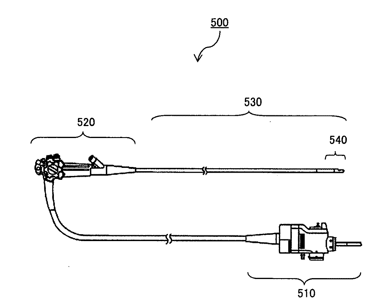
[0092]FIG. 5 shows an external configuration of an ultrasonic endoscope according to the present embodiment. The ultrasonic endoscope 1 comprises an operation part 6 at the base end of a slender insertion part 2. From a side part of the operation part 6 extends a universal cord 7 to be connected to a light source apparatus (not shown herein).

[0093]The insertion part 2 is constituted of connecting, in sequence starting at the head part, a head part 3, a bending part 4 that actuates bending and a flexible tube part 5 having flexibility. The operation part 6 is equipped with a curvature operation knob 6a and the bending part 4 can be bent by operating the curvature operation knob 6a.

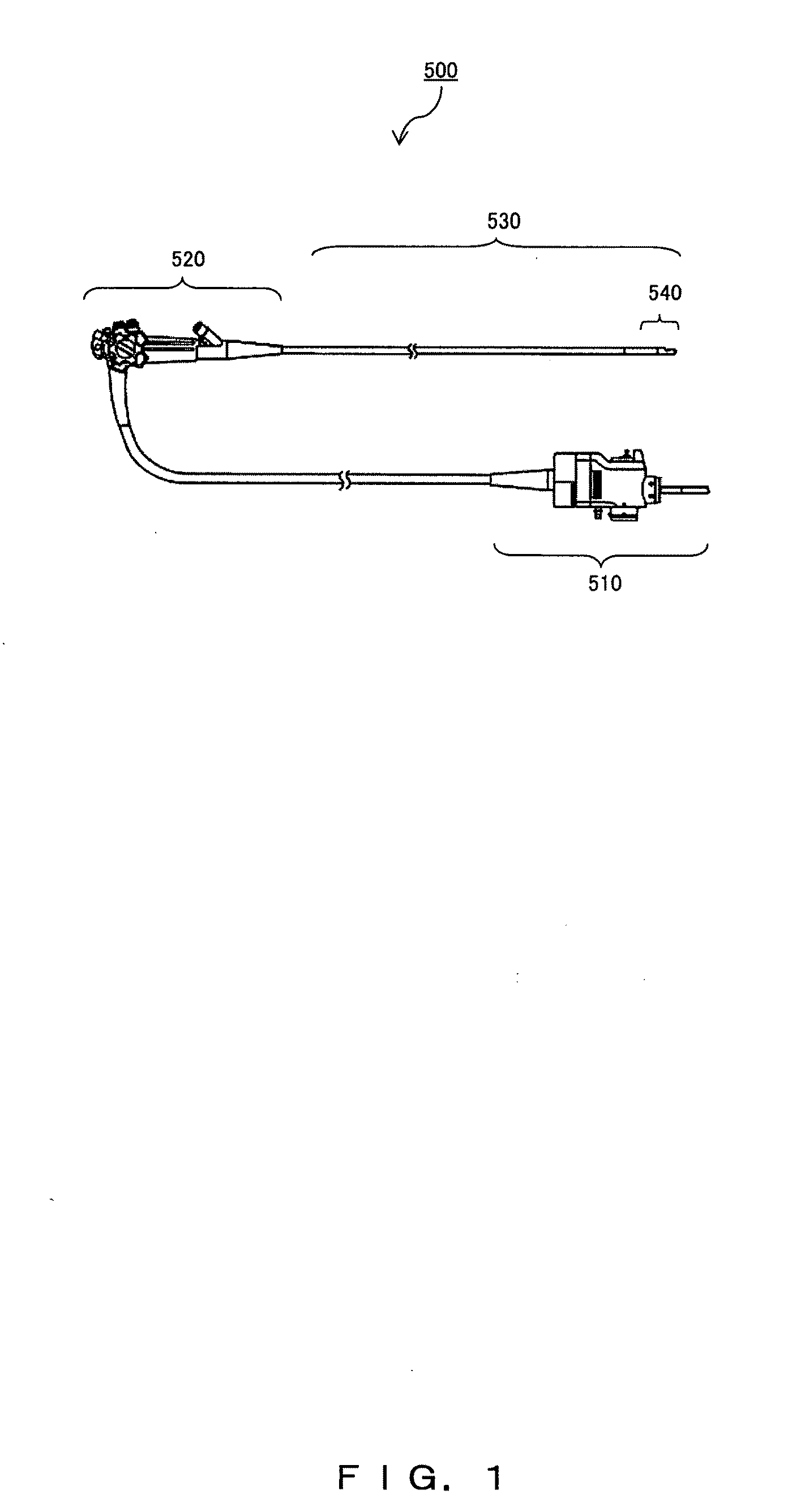
[0094]FIG. 6 is an enlarged diagram of the head part 3 of the ultrasonic endoscope 1 shown in FIG. 5. The head part 3 is equipped with an ultrasonic transducer 10 enabling an electronic radial type scan, and an inclination part 12 is equipped in between the bending part 4 and ultrasonic transducer 10. The ...


PUM

PropertyMeasurementUnit
Thicknessaaaaaaaaaa
Thicknessaaaaaaaaaa
Thicknessaaaaaaaaaa

Abstract

An electronic radial type ultrasonic transducer arraying, in a cylindrical form, a plurality of ultrasonic transducer elements for transmitting and receiving ultrasound, and for storing cables corresponding to the respective ultrasonic transducer elements for transmitting a drive signal for driving each of the ultrasonic transducer elements in the inside of a group of the ultrasonic transducer elements arrayed in the cylindrical form, featuring a conductive film on a surface of an insulator through which the cable group is led, and also comprising an acoustic lens constituted of a lens part which is connected to a ground wire and featured as a convex form and a cover part covering an easily breakable part or conductor material which is electrically connected to a plurality of ultrasonic transducers.

Description

TECHNICAL FIELD[0001]The present invention relates to an electronic radial scanning type ultrasonic transducer.BACKGROUND ART[0002]An electronic scanning type ultrasonic transducer is equipped on a part of an endoscope that is inserted into an abdomen, the use of which makes it possible to extract a clear image of a digestive canal wall and deep organs such as the pancreas, gallbladder, et cetera, in a good image quality without being negatively influenced by abdominal gasses or bone. The electronic scanning type ultrasonic transducer is constituted of no less than tens of elements and a number of coaxial cables for transmission and reception equivalent to the number of elements. When connecting an electrode of each element of the electronic scanning type ultrasonic transducer to a signal transmission / reception-use coaxial cable, a common method is to solder a core lead of the coaxial cable to a signal electrode of each element and solder a shield wire of the coaxial cable to a grou...

Claims


Application Information

Patent Timeline
IPC IPC(8): A61B8/14H04R31/00
CPCA61B8/12Y10T29/49005A61B8/445B06B1/0633
Inventor WAKABAYASHI, KATSUHIROSAWADA, YUKIHIKOMIZUNUMA, AKIKOIMAHASHI, TAKUYASATO, SUNAOFUJIMURA, TAKANAO
Owner OLYMPUS CORP
Why Eureka
Try Eureka