Optical Scanning Probe

a scanning probe and optical technology, applied in the field of noncontact optical scanning, can solve the problems of high cost of operation, marketplace situation, human operator's human error, etc., and achieve the effect of increasing the speed of scanning

Active Publication Date: 2009-08-13
3D SCANNERS LTD
View PDF9 Cites 59 Cited by
  • Summary
  • Abstract
  • Description
  • Claims
  • Application Information

AI Technical Summary

Benefits of technology

[0104]In a further embodiment of the present invention, a tracking win

Problems solved by technology

Manual CMM Arms are acceptably accurate for many applications, but are not automated; they are expensive to operate, particularly since a semi-skilled operator is required; human operators are also subject to human error.
The marketplace is in the situation of not being able to perform standar

Method used


Image

  • Optical Scanning Probe
  • Optical Scanning Probe
  • Optical Scanning Probe

Examples


Embodiment Construction

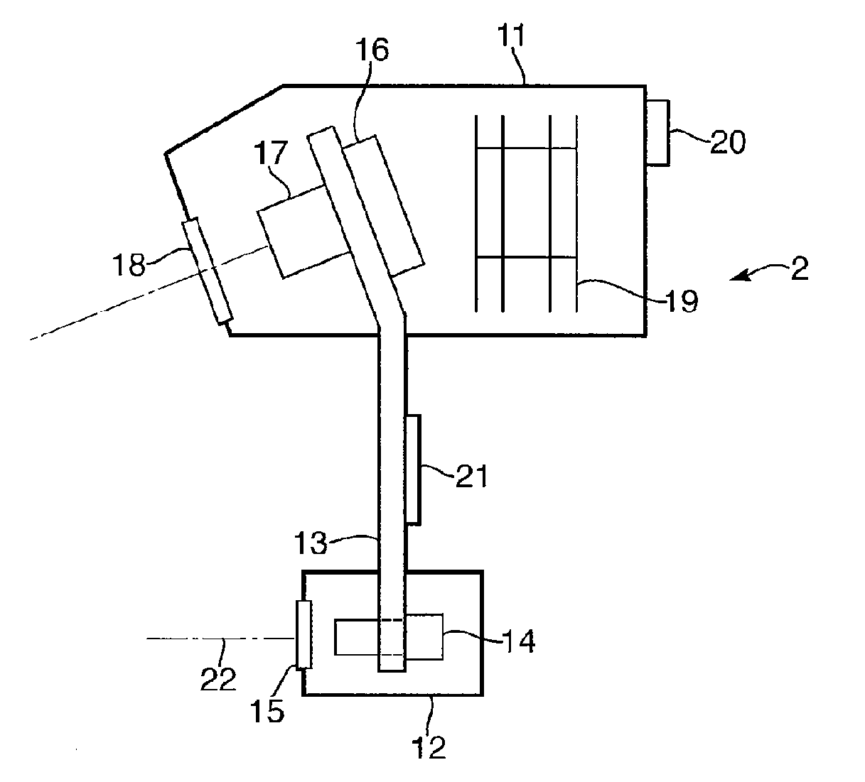
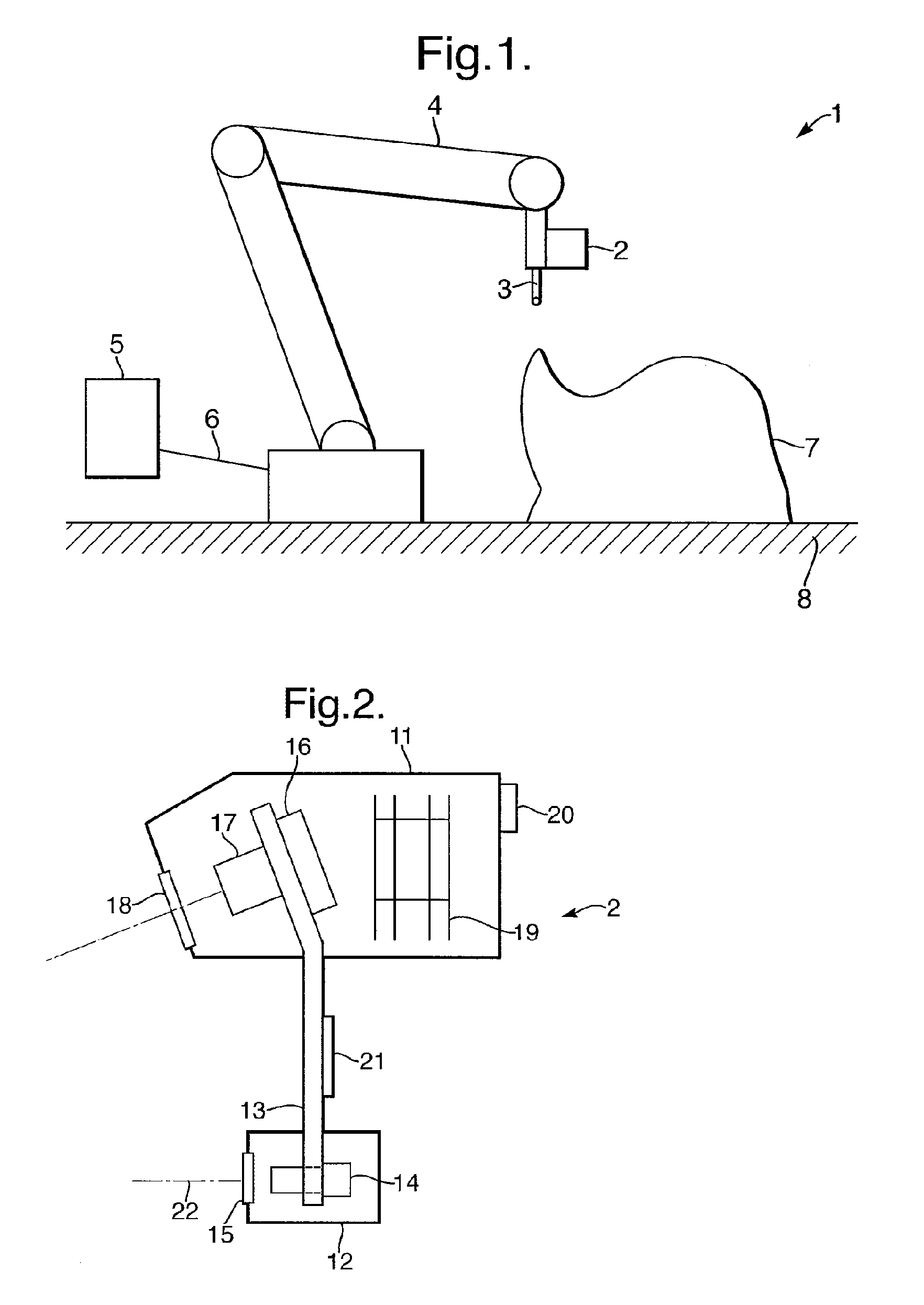
[0014]One embodiment of the invention relates to a scanning probe (2) for capturing data from a plurality of points on the surface of an object by irradiating the object with a light stripe and detecting light reflected from the object surface, the scanning probe comprising:

(a) stripe generating means (14) for generating and emitting a light stripe (55);

(b) a camera (16) comprising an imaging sensor having an array of pixels to detect the light stripe reflected from the object surface;

(c) means for adjusting the intensity of the light stripe (55) during acquisition of a single frame, in dependence upon the intensities detected by the camera (16).

[0015]Another embodiment of the invention relates to a scanning probe (2) as described above, wherein:[0016]the camera (16) and / or stripe generating means (14) are configured such that different subsets of the imaging sensor pixels at different times detect light reflected from the stripe during the acquisition of the frame, the different su...


PUM


Abstract

The present invention relates to a scanning probe (2) for capturing data from a plurality of points on the surface of an object by irradiating the object with a light stripe and detecting light reflected from the object surface, the scanning probe comprising (a) stripe generating means (14) for generating and emitting a light stripe (55); (b) a camera (16) comprising an imaging sensor having an array of pixels to detect the light stripe reflected from the object surface: (c) means for adjusting the intensity of the light stripe (55) during acquisition of the frame, in dependence upon the intensities detected by the camera (16). It also relates to a means to modify the stripe length, a scanner with separate compartment for the processing means, and an attachable dust cover for a scanner.

Description

FIELD OF THE INVENTION[0001]The present invention concerns non-contact optical scanning.BACKGROUND TO THE INVENTIONScanning Probes[0002]Scanning probes are non-contact optical probes for measuring thousands of points a second on the 3D surface shape of an object. There are three broad types of scanning probe: point, stripe and area. This invention concerns stripe scanning probes. Most stripe scanning probes use the principal of optical triangulation. Stripe scanning probes are provided or are being developed by Metris (Belgium), 3D Scanners (UK), Romer (France), Faro Technologies (USA), Perceptron (USA), Steinbichler (Germany), Pulstec (Japan), Micro Epsilon (Germany), SICK IVP (Germany), Vitana (Canada), Laser Design (USA), Datapixel (Spain), Optimet (Israel) and Kreon (France) amongst others.Movement of Stripe Scanning Probes[0003]In order to scan the surface of an object a stripe scanning probe needs to move over the object's surface in a similar way to how a paintbrush is used f...

Claims


Application Information

Patent Timeline
IPC IPC(8): G12B21/02G01Q60/00
CPCG01B11/2518
Inventor CRAMPTON, STEPHEN JAMESCHAMP, PETER
Owner 3D SCANNERS LTD
Why Eureka
Try Eureka