[0007]The nature of the explosion is an important factor in determining the overall cost of an explosion forming
system. In one broad aspect of the invention, an explosion forming
system is provided where the
system generates a
shock wave that is progressively applied to a work piece. This enables the
tonnage required to press or seal a conforming die for the work piece to be reduced in comparison to other pressure forming systems such as hydro-forming systems or other explosion forming systems. This is primarily due to the fact that the force of the
shock wave, although relatively high as discussed in detail herein, is applied over a relatively small area of the work piece and underlying die at any point in time, and thus the power required to press the die can be reduced in comparison to prior art pressure forming systems. Smaller
tonnage means reduced capital costs. In addition, by progressively applying a shock wave, it is easier to punch relatively small holes in the work piece and / or trim sections of the work piece in comparison to the prior art.
[0014]As discussed in detail herein, another factor in reducing the
tonnage required to press the die in an explosion forming system lies in the after pressure or
back pressure resulting from the gaseous products of
combustion. To minimize such after pressure, it is desirable to use a stoichiometric ratio of
oxygen and
hydrogen to produce water vapour, and to cool the ignition chamber in order to rapidly condense the water vapour and hence reduce the after pressure.
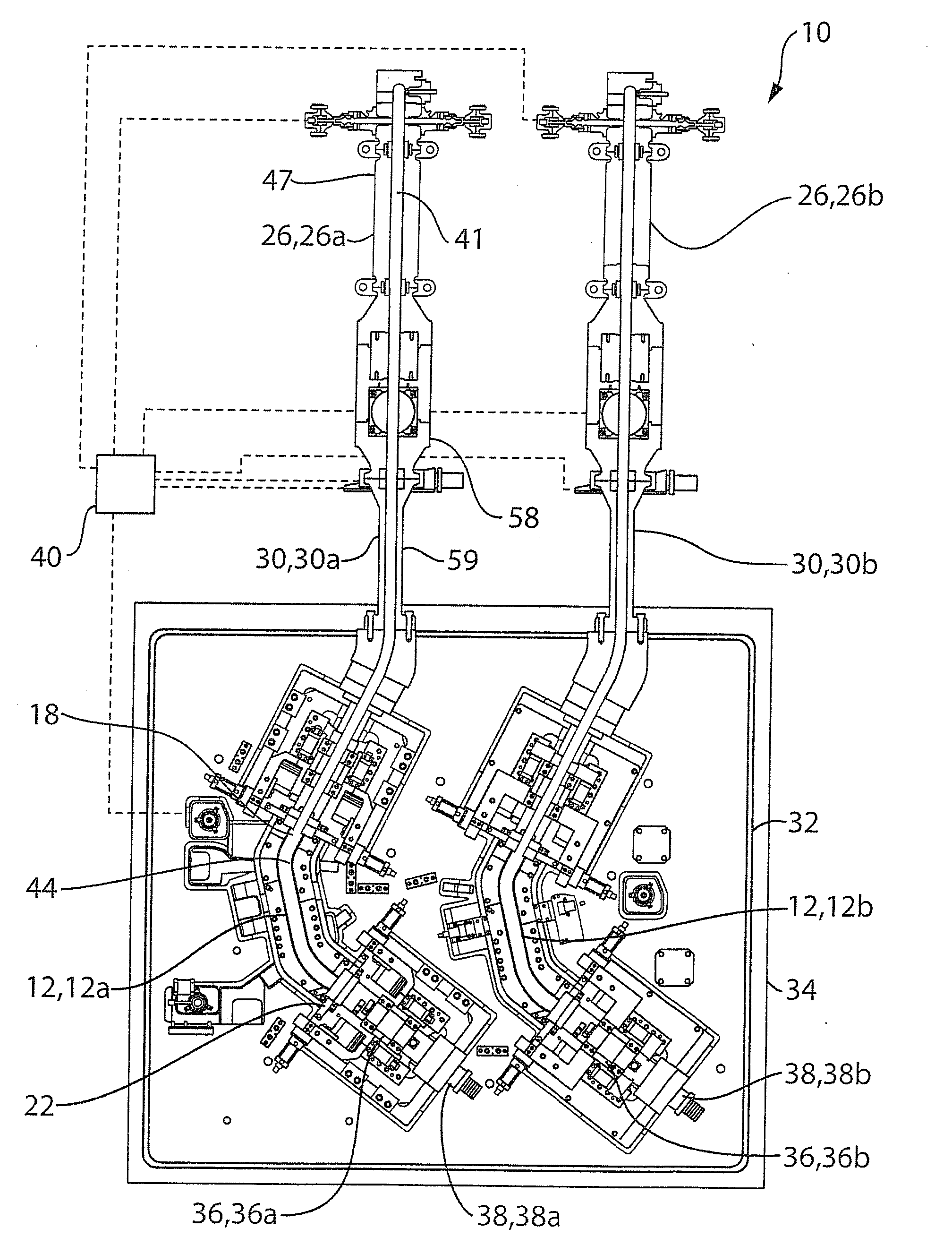
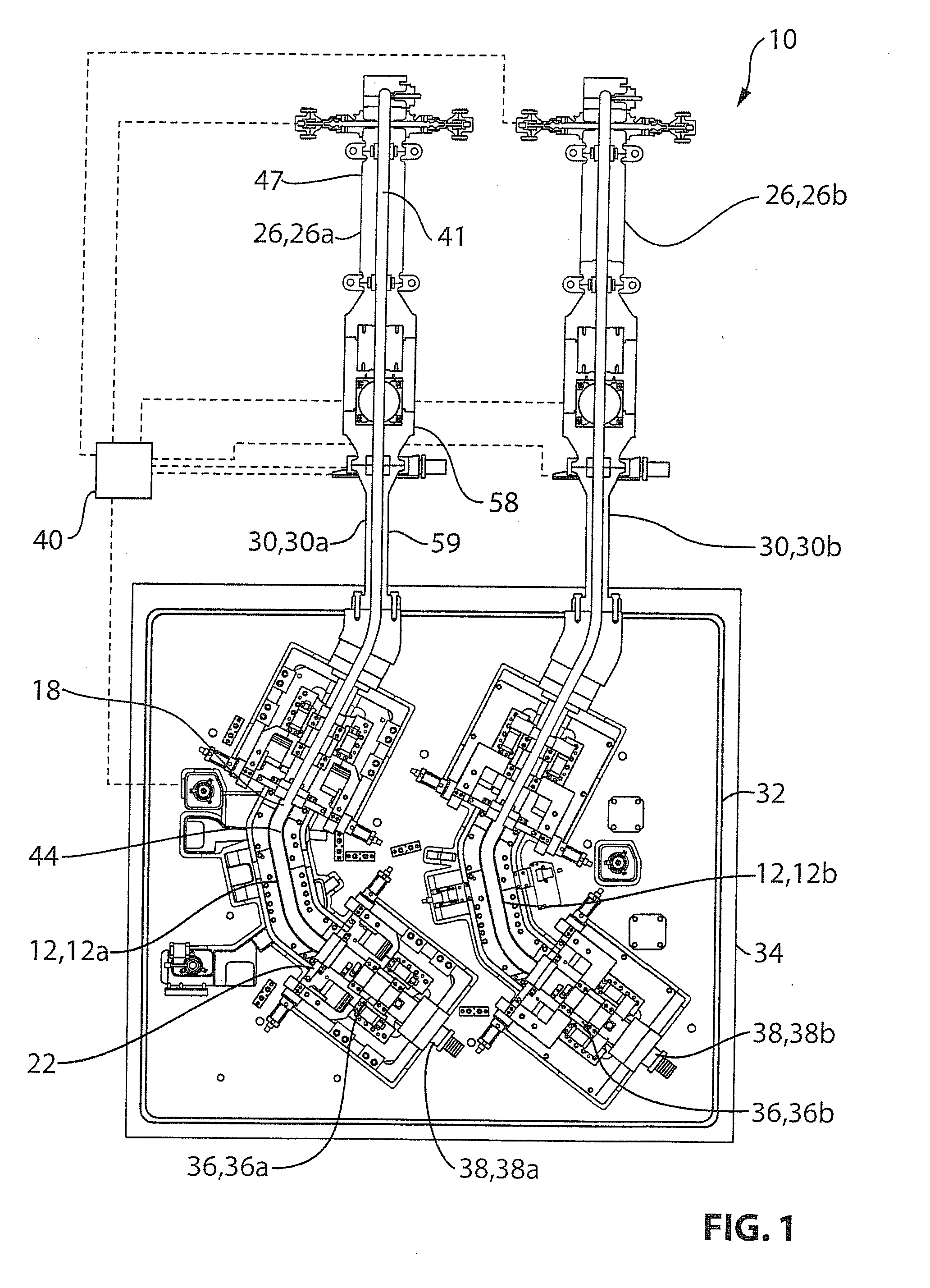
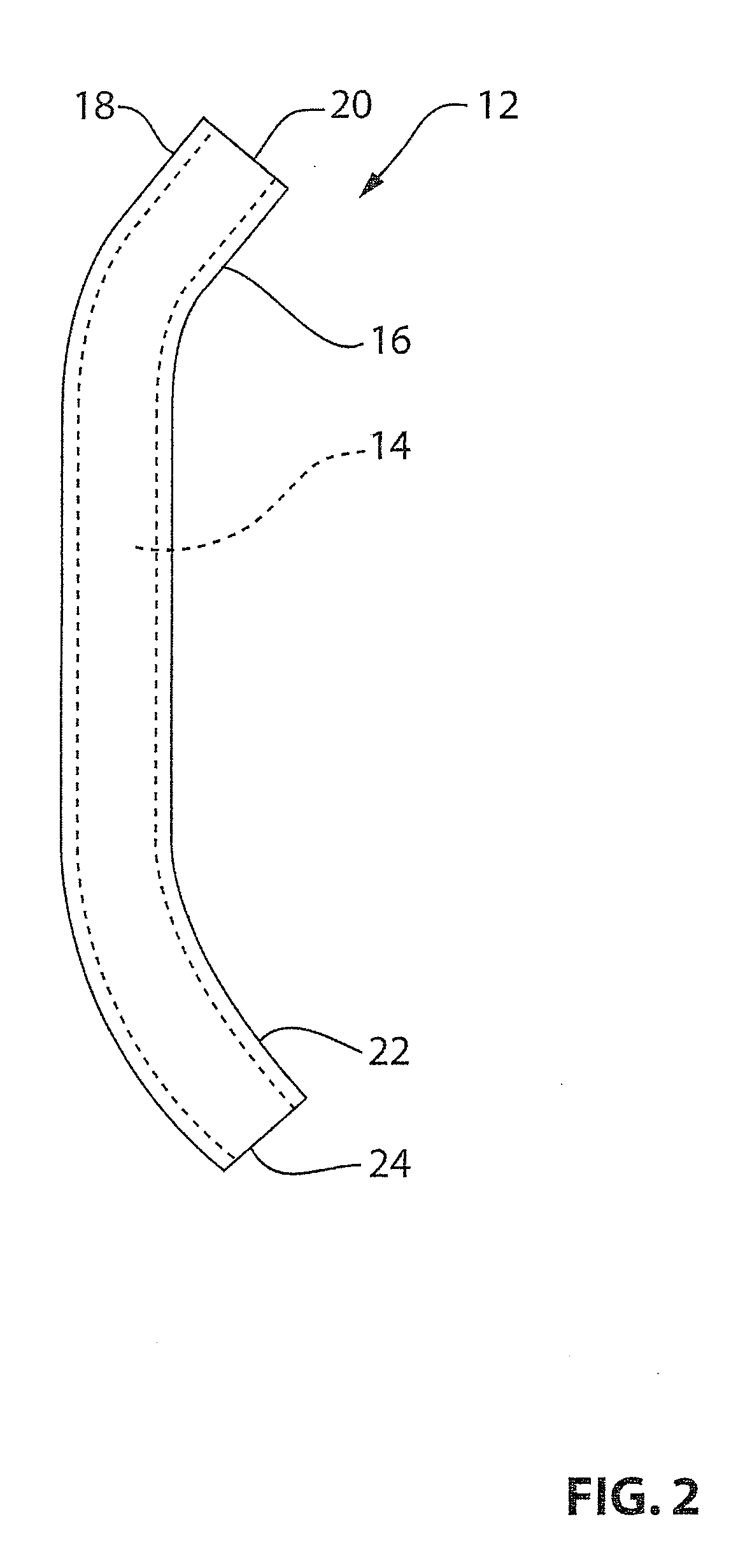
[0016]Sixth, an apparatus for modifying a tubular work piece defining a conduit length. The apparatus includes: an ignition chamber configured for generating a shock wave that has a shock wave length that is less than the conduit length of the work piece, wherein the ignition chamber utilizes
oxygen and
hydrogen as combustibles and includes at least one combustibles inlet; an igniter; a die, wherein the die includes a first die plate and a second die plate, wherein at least one of the first and second die plates is movable relative to the other between an open position and a closed position wherein the first and second die plates together define a die cavity in which the work piece can be positioned, wherein, in operation, the shock wave travels through the work piece and applies a localized pressure to the work piece in a direction that is transverse to the shock wave travel path, and wherein the die is holdable in the closed position by a selected die holding force against pressure in the work piece; a transfer structure configured to convey the shock wave from the ignition chamber into the work piece to modify the work piece; a controller for the transfer of a selected ratio and quantity of
oxygen and
hydrogen combustibles into the ignition chamber and for actuating the igniter to react the combustibles, wherein the controller serially executes explosions; and a cooling system for cooling the ignition chamber so as to reduce the pressure of water vapour created by reacting oxygen and hydrogen.
[0017]Seventh, an apparatus for modifying a work piece having a longitudinal length. The apparatus includes: an ignition chamber configured for generating a traveling shock wave that has a shock wave length that is less than the longitudinal length of the work piece, wherein the ignition chamber utilizes oxygen and hydrogen combustibles to generate the shock wave and includes at least one combustibles inlet; an igniter; a die, wherein the die includes a first die plate and a second die plate, wherein at least one of the first and second die plates is movable relative to the other between an open position and a closed position wherein the first and second die plates together define a die cavity in which the work piece can be positioned; a transfer structure configured to convey the shock wave from the ignition chamber into the die cavity; wherein, in operation, the shock wave applies a localized pressure to the work piece in a direction that is transverse to the direction of travel of the shock wave, and wherein the die is holdable in the closed position by a selected die holding force; a controller for the transfer of a selected ratio and quantity of oxygen and hydrogen into the ignition chamber and for actuating the igniter to react the combustibles, wherein the controller serially executes explosions; and a cooling system for cooling the ignition chamber so as to reduce the pressure of water vapour created by reacting oxygen and hydrogen.
[0045]In addition, some embodiments of the explosion forming system minimize
cycle time by producing a finished work piece that may not require additional
processing steps such as such as
cutting or trimming. For instance, one system described herein accurately forms and / or pierces and trims work pieces to produce finished parts, thus not requiring subsequently trimming the ends of work pieces with lasers or other
cutting implements that can require a significant period of time to carry out, especially when the work piece is formed from
high strength steel.
[0049]One of the hallmarks of a
production quality explosion forming system is the ability to rapidly produce parts of consistent quality. To do that, the explosion and the pressure generated by the system should be held relatively constant on every run or execution. It was discovered that the temperature of the combustibles could have a deleterious effect on the
production rate and the quality of the parts produced.

