
Steering fabric that facilitates reducing power use for proximity communication

a technology of proximity communication and steering fabric, which is applied in the direction of semiconductor devices, semiconductor/solid-state device details, conductors, etc., can solve the problems of increasing power consumption, reducing inter-chip communication performance, and high cost of providing such circuitry to steer data, so as to facilitate reducing the power needed for proximity communication, reduce the power needed to transmit the signal, and eliminate redundant steering configurations

Active Publication Date: 2009-08-20
ORACLE INT CORP
View PDF26 Cites 15 Cited by
  • Summary
  • Abstract
  • Description
  • Claims
  • Application Information

AI Technical Summary

Benefits of technology

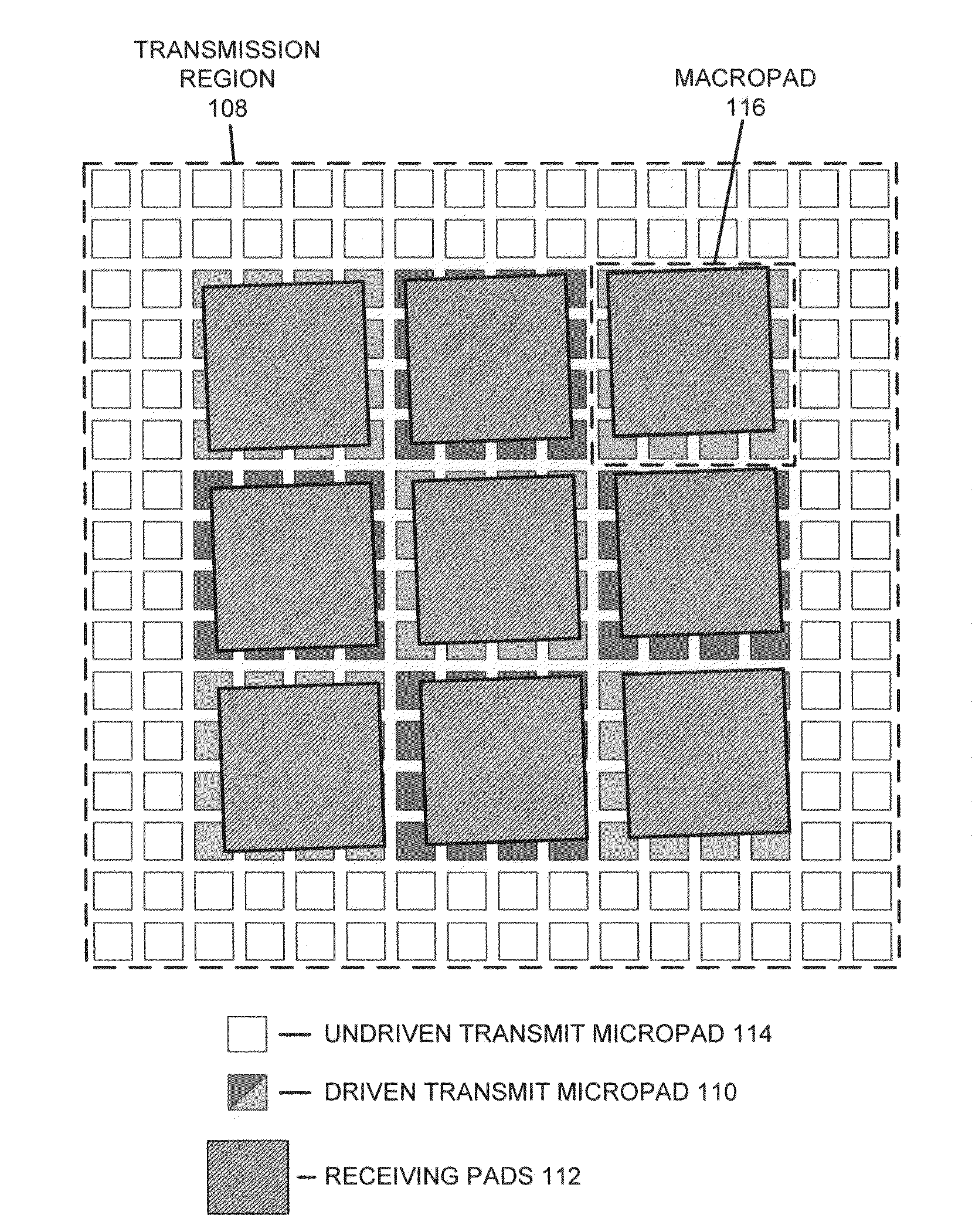
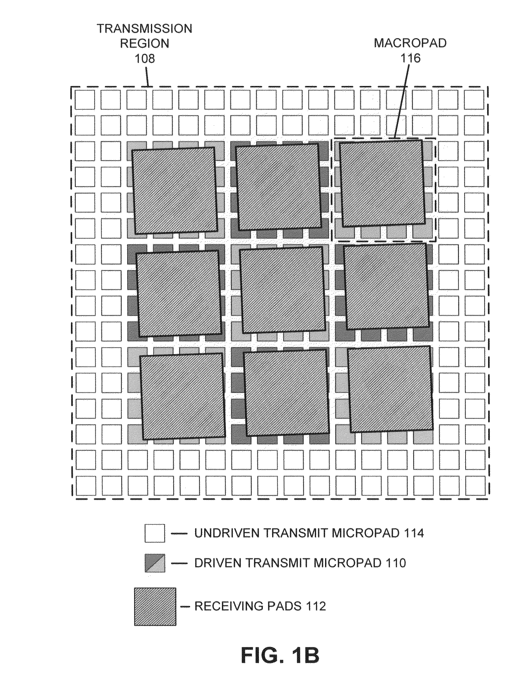
[0009]One embodiment of the present invention provides a system that facilitates reducing the power needed for proximity communication. This system includes an integrated circuit with an array of transmission pads that transmit signals using proximity communication. This array is comprised of a set of macropads, where each given macropad is comprised of a set of micropads that can be configured to transmit a signal. A steering fabric routes signals to and within macropads, such that a subset of the micropads in the array can be configured to transmit the signal to a receiving component. Each macropad receives a limited number of input signals, with the steering fabric routing input signals to the micropads of the macropads. By limiting the number of input signals that are routed to the micropads of the macropads, the steering fabric eliminates redundant steering configurations for the array and reduces the power needed to transmit the signal.
[0010]In some embodiments, the limited number of input signals received by each given macropad is less than the number of micropads in each macropad. Some of the input signals for a given macropad may be routed to a limited set of micropads in the macropad. Reducing the number of input signals that can be routed to a micropad simplifies the steering logic for the given macropad and facilitates reducing the power needed to transmit the signal.
[0013]In some embodiments, the steering fabric facilitates electronic alignment techniques that use a set of micropads that span multiple macropads to transmit a signal to the receiving component using proximity communication.
[0014]In some embodiments, a redundant steering configuration occurs when multiple different sets of input values for the steering fabric result in the same configuration of transmit values for the array. Eliminating redundant steering configurations reduces the complexity and power usage of the steering fabric while still allowing signals transmitted by the micropads to be electronically aligned to match a full range of receiving component locations.
[0015]In some embodiments, the different micropads in a given macropad have different probabilities of being driven by a given input signal. A signal line that carries an input signal can be routed in proximity to micropads that are more likely to be driven by that input signal, thereby reducing the average parasitic capacitance between the signal line and micropads that are more likely to be driven by other input signals.

Problems solved by technology

Because sub-optimal alignment can reduce inter-chip communication performance and increase power consumption, some proximity communication systems employ electronic alignment techniques that dynamically correct the alignment of components to compensate for mechanical misalignment.
Unfortunately, providing such circuitry to steer data is costly and consumes additional power.
A row and / or a column of micropads in this rectangular grid may be limited to receive two or fewer input signals.

Method used


Image

  • Steering fabric that facilitates reducing power use for proximity communication
  • Steering fabric that facilitates reducing power use for proximity communication
  • Steering fabric that facilitates reducing power use for proximity communication

Examples


Embodiment Construction

[0050]The following description is presented to enable any person skilled in the art to make and use the embodiments, and is provided in the context of a particular application and its requirements. Various modifications to the disclosed embodiments will be readily apparent to those skilled in the art, and the general principles defined herein may be applied to other embodiments and applications without departing from the spirit and scope of the present disclosure. Thus, the present invention is not limited to the embodiments shown, but is to be accorded the widest scope consistent with the principles and features disclosed herein.

[0051]The data structures and code described in this detailed description are typically stored on a computer-readable storage medium, which may be any device or medium that can store code and / or data for use by a computer system. The computer-readable storage medium includes, but is not limited to, volatile memory, non-volatile memory, magnetic and optical...


PUM

PropertyMeasurementUnit
lengthsaaaaaaaaaa
lengthsaaaaaaaaaa
threshold voltageaaaaaaaaaa

Abstract

One embodiment of the present invention provides a system that facilitates reducing the power needed for proximity communication. This system includes an integrated circuit with an array of transmission pads that transmit signals using proximity communication. This array is comprised of a set of macropads, where each given macropad is comprised of a set of micropads that can be configured to transmit a signal. A steering fabric routes signals to and within macropads, such that a subset of the micropads in the array can be configured to transmit the signal to a receiving component. Each macropad receives a limited number of input signals, with the steering fabric routing input signals to the micropads of the macropads. By limiting the number of input signals that are routed to the micropads of the macropads, the steering fabric eliminates redundant steering configurations for the array and reduces the power needed to transmit the signal.

Description

RELATED APPLICATION[0001]This application claims the benefit of U.S. Provisional Application No. 61 / 024,472, entitled “Power Optimized Techniques for Electronic Alignment Correction,” by inventors Alex Chow, Robert J. Drost, and Ronald Ho, filed on 29 Jan. 2008 (Attorney Docket No. SUNO7-0096-PSP). The subject matter of this application is also related to the subject matter in a co-pending non-provisional application by the same inventors as the instant application, entitled “A Circuit that Facilitates Proximity Communication,” having Ser. No. 12 / 215,943, and filed on 30 Jun. 2008 (Attorney Docket No. SUN07-0096). The subject matter of this application is also related to the subject matter in a co-pending non-provisional application by the same inventors as the instant application and filed on the same day as the instant application, entitled “Using Floating Fill Metal to Reduce Power Use for Proximity Communication,” having serial number TO BE ASSIGNED, and filing date of 24 Dec. 2...

Claims


Application Information

Patent Timeline
Patent Type & Authority Applications(United States)
IPC IPC(8): H01B5/00
CPCH01L23/48H01L2225/06527H01L2924/0002H01L2924/00
Inventor CHOW, ALEXDROST, ROBERT J.HO, RONALDPROEBSTING, ARLENEPROEBSTING, ROBERT
Owner ORACLE INT CORP
Learn More