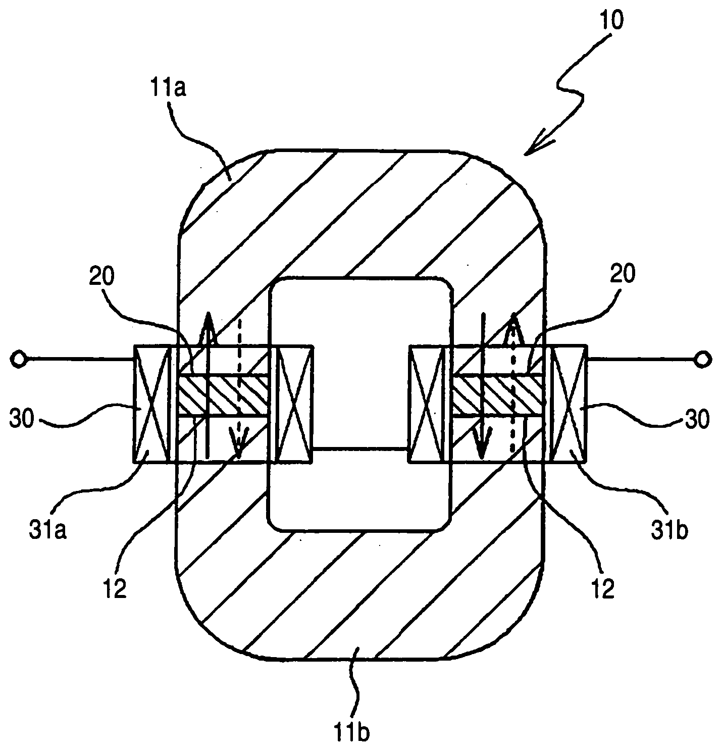
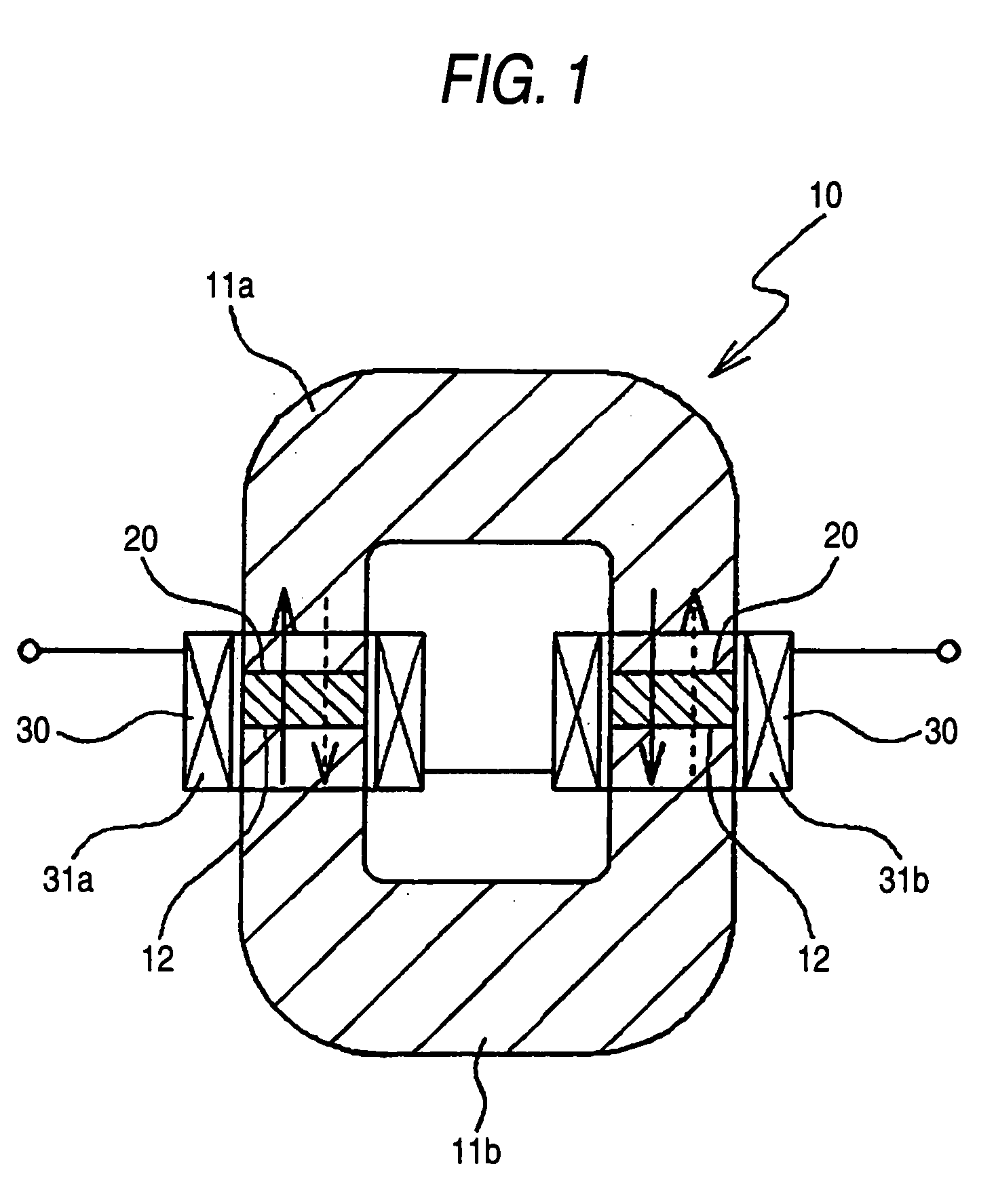
Bond magnet for direct current reactor and direct current reactor
a direct current reactor and bond magnet technology, applied in the direction of magnets, transformers/inductances, magnet bodies, etc., can solve the problems of ineffective product delivery, inability to meet the requirements of direct current voltage output, and conventional techniques, so as to reduce the in-gap vibration and reduce the noise
- Summary
- Abstract
- Description
- Claims
- Application Information
AI Technical Summary
Benefits of technology
Problems solved by technology
Method used
Image

Examples
example 1b
[0070]Raw materials were weighed to achieve a magnet alloy composition of Nd: 30.4 mass %, Fe: 62.0 mass %, Co: 6.00 mass %, B: 0.91 mass %, Ga: 0.56 mass %, and inevitable impurities: 0.13 mass %, and the weighed materials were heated and molten to obtain a molten alloy.
[0071]Subsequently, the thus-obtained molten alloy was rapidly solidified by using the single roll rapid quenching method to prepare a rapidly quenched powder having the above-described magnet alloy composition (average grain diameter: 200 μm). A roll rim speed was 25 m / s.
[0072]Subsequently, 97 mass % of the thus-obtained rapidly quenched powder and 3 mass % of an epoxy resin serving as a binder were mixed.
[0073]Subsequently, the thus-obtained mixture was molded into a rectangular parallelepiped article having a thickness of 1 mm, a length of 25 mm, and a width of 16 mm by employing press molding. After that, a hardening treatment was performed in an argon atmosphere at 170° C. for one hour, followed by magnetizatio...
example 2b
[0075]Raw materials were weighed to achieve a magnet alloy composition of Sm: 19.3 mass %, Fe: 72.0 mass %, N: 3.1 mass %, and inevitable impurities: 5.6 mass %, and the weighed materials were heated and molten to obtain a molten alloy.
[0076]A bond magnet according to Example 2B was obtained in the same manner as in the bond magnet production according to Example 1B except for using the molten alloy of the magnet alloy composition prepared in Example 2B. The bond magnet according to Example 2B had a residual magnetic flux density of 0.75 T and a coercive force of 1220 kA / m.
example 3b
[0077]Raw materials were weighed to achieve a magnet alloy composition of Sm: 30.0 mass % and Co: 70.0 mass %, and the weighed materials were heated and molten to obtain a molten alloy.
[0078]A bond magnet according to Example 3B was obtained in the same manner as in the bond magnet production according to Example 1B except for using the molten alloy of the magnet alloy composition prepared in Example 3B. The bond magnet according to Example 3B had a residual magnetic flux density of 0.60 T and a coercive force of 1350 kA / m.
PUM
| Property | Measurement | Unit |
|---|---|---|
| temperature | aaaaa | aaaaa |
| residual magnetic flux density | aaaaa | aaaaa |
| grain diameter | aaaaa | aaaaa |
Abstract
Description
Claims
Application Information
 - R&D
- Intellectual Property
- Life Sciences
- Materials
- Tech Scout
- Unparalleled Data Quality
- Higher Quality Content
- 60% Fewer Hallucinations
Browse by: Latest US Patents, China's latest patents, Technical Efficacy Thesaurus, Application Domain, Technology Topic, Popular Technical Reports.
© 2025 PatSnap. All rights reserved.Legal|Privacy policy|Modern Slavery Act Transparency Statement|Sitemap|About US| Contact US: help@patsnap.com