Magneto-resistance effect element including stack with dual free layer and magnetized shield electrode layers

a shield electrode layer and magneto-resistance effect technology, which is applied in the field of element structure of a magnetoresistance-resistance-effect element having a dual-free layer, can solve the problems of difficult to increase the magneto-resistance ratio, difficult to generate anti-ferromagnetic exchange coupling between the upper magnetic layer and the lower magnetic layer, and difficult to improve the output of the magneto-resistance-effect element. , to achieve th

Inactive Publication Date: 2009-08-20
TDK CORPARATION
View PDF9 Cites 19 Cited by
  • Summary
  • Abstract
  • Description
  • Claims
  • Application Information

AI Technical Summary

Benefits of technology

[0010]The present invention is for a CPP-type magneto-resistance effect element having dual free layer. The object of the present invention is to provide a CPP-type magneto-resistance effect element in which it is possible to realize anti-parallel magnetization state in a pair of free layers. A further object of the present invention is to improve detection properties of the above-described magneto-resistance effect element by improving the shielding effects of shield electrode layers and reducing variation in the magnetization directions in the free layers.

Problems solved by technology

However, when the non-magnetic intermediate layer is composed of these materials, it is difficult to increase the magneto-resistance ratio.
As a result, it is difficult to improve the output of the magneto-resistance effect element.
However, with these materials, it is extremely difficult to generate anti-ferromagnetic exchange coupling between the upper magnetic layer and the lower magnetic layer.
Consequently, there is an undesired increase in the layer thickness of the MR stack.
Also, while it is necessary to set the directions of the exchange coupling generated by the two anti-ferromagnetic layers to be anti-parallel, the heat treatment (annealing) to realize this arrangement is very difficult.
Moreover, when the element size is reduced, the pinning function ceases to be sufficiently effective and it becomes difficult to partition the upper and lower magnetic layers into single domains.
Consequently, there is problem in that Barkhausen noise which accompanies the movement in the magnetic domain walls of the upper and lower magnetic layers causes variation in the output characteristics.

Method used


Image

  • Magneto-resistance effect element including stack with dual free layer and magnetized shield electrode layers
  • Magneto-resistance effect element including stack with dual free layer and magnetized shield electrode layers
  • Magneto-resistance effect element including stack with dual free layer and magnetized shield electrode layers

Examples


Embodiment Construction

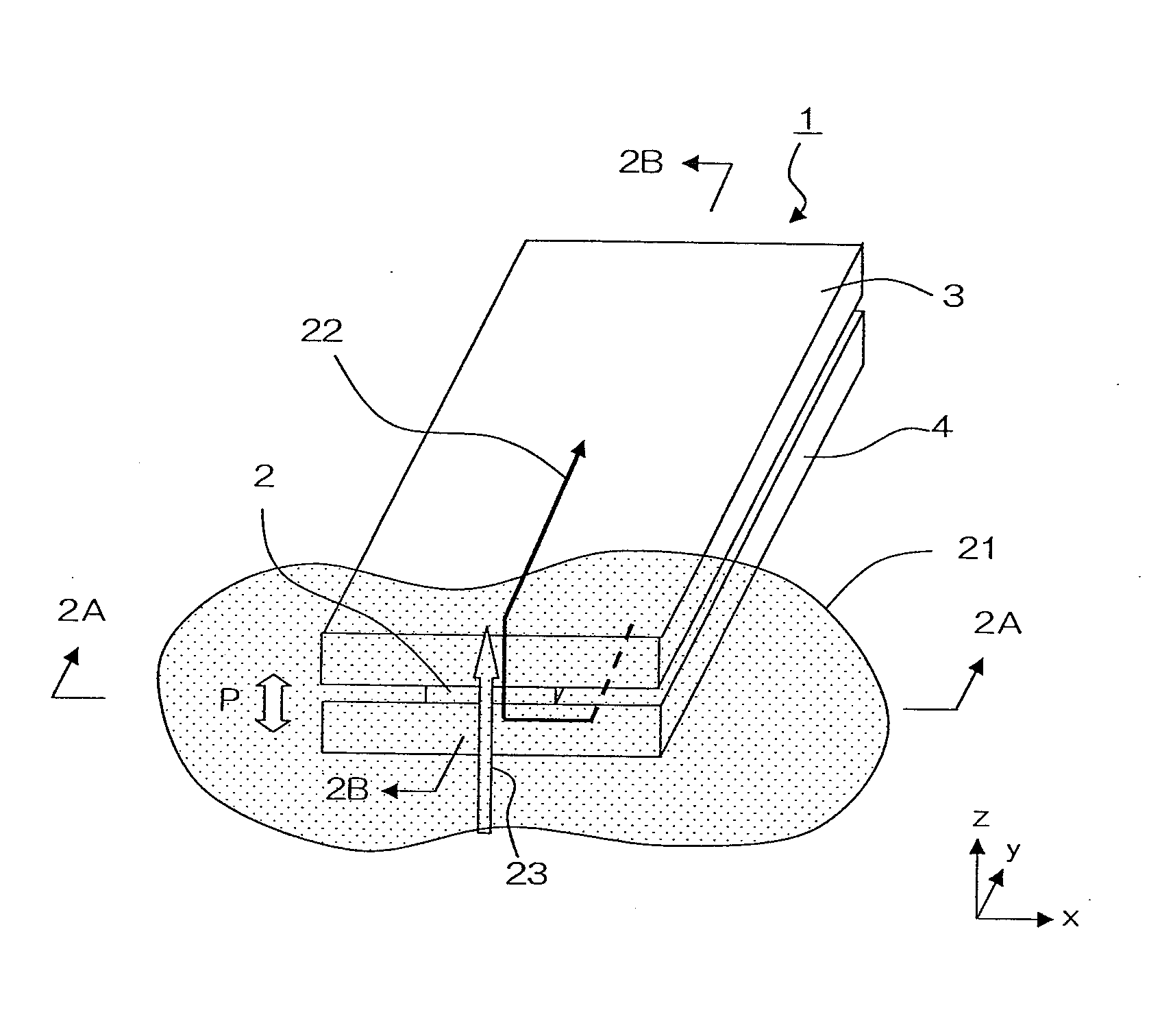
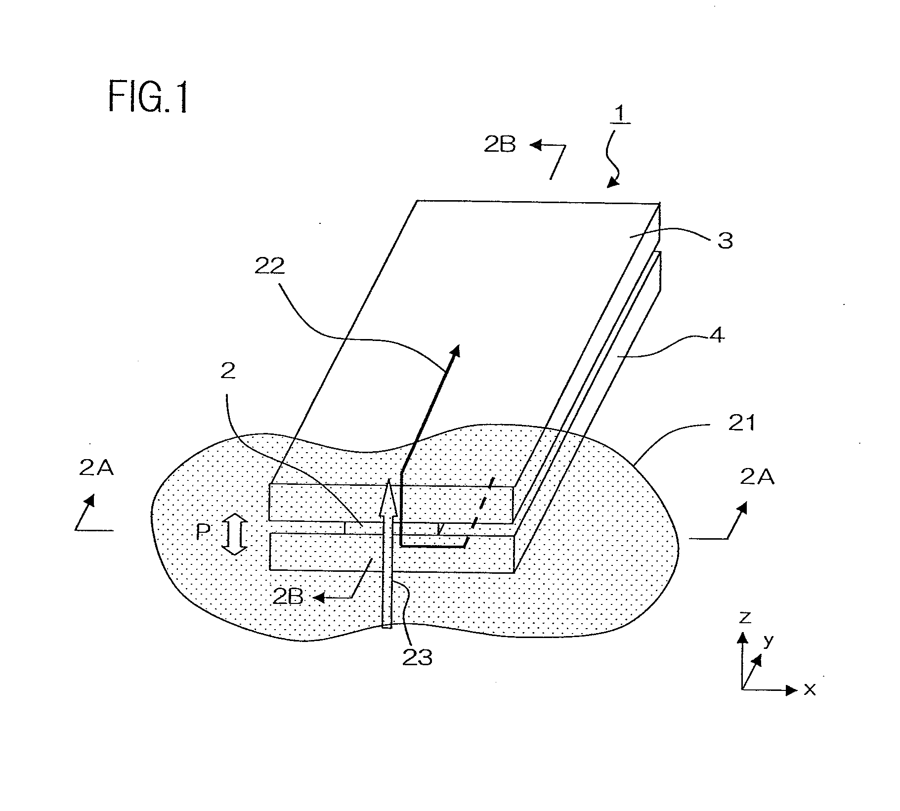
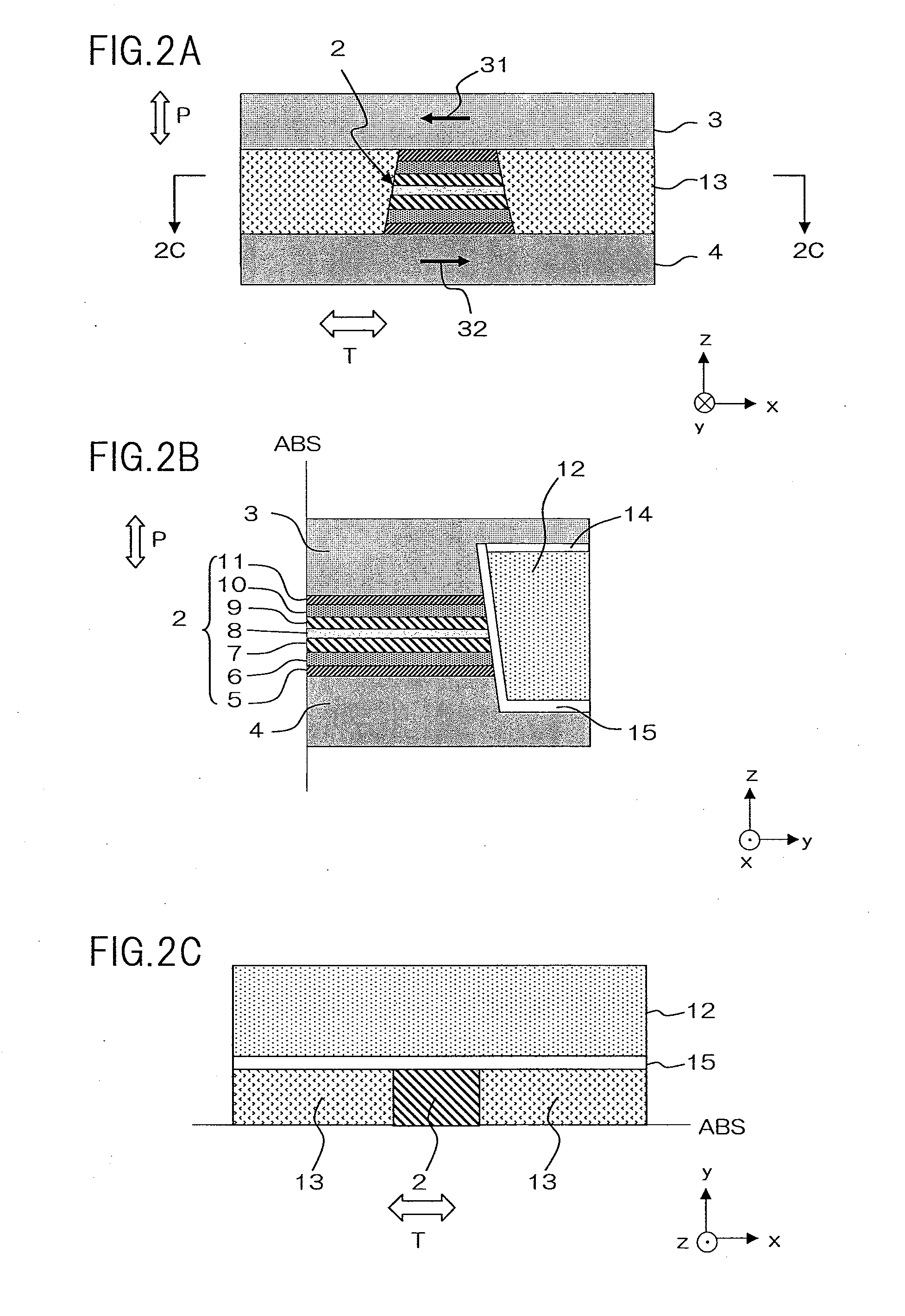
[0033]The following describes one embodiment of the present invention with reference to the drawings. A magneto-resistance effect element of the present embodiment is particularly suitable for use as a read head portion of a thin film magnetic head of a hard disc drive. FIG. 1 is a schematic perspective drawing of the magneto-resistance effect element of the present embodiment. FIG. 2A is a side elevation of the magneto-resistance effect element as seen from the 2A-2A direction in FIG. 1, which is to say, from an air bearing surface (a surface lying parallel to the z-x plane in the drawing). FIG. 2B is a cross-sectional view of the magneto-resistance effect element along the 2B-2B line in FIG. 1, which is to say at a surface perpendicular to a track width direction T (a surface lying parallel to the y-z plane in the drawing). FIG. 2C is a cross-sectional view of the magneto-resistance effect element along the 2C-2C line in FIG. 2A, which is to say, at a surface aligned with the laye...


PUM

PropertyMeasurementUnit
thicknessaaaaaaaaaa
thicknessaaaaaaaaaa
thicknessaaaaaaaaaa

Abstract

A magneto-resistance effect element comprises; a magneto-resistance effect stack including an upper magnetic layer and a lower magnetic layer in which respective magnetization directions change in accordance with an external magnetic field, a non-magnetic intermediate layer sandwiched between the upper and lower magnetic layers, an upper gap adjustment layer and a lower gap adjustment layer provided at respective ends in the direction of stacking the magneto-resistance effect stack, an upper exchange coupling transmission layer configured to generate exchange coupling between the upper magnetic layer and the upper gap adjustment layer, and a lower exchange coupling transmission layer configured to generate exchange coupling between the lower magnetic layer and the lower gap adjustment layer; an upper shield electrode layer and a lower shield electrode layer which are provided to sandwich the magneto-resistance effect stack therebetween in the direction of stacking the magneto-resistance effect stack, wherein the upper shield electrode layer and the lower shield electrode layer supply sense current in the direction of stacking, and magnetically shield the magneto-resistance effect stack; and a bias magnetic layer which is provided on a surface of the magneto-resistance effect stack opposite to an air bearing surface, and wherein the bias magnetic layer applies a bias magnetic field to the upper and lower magnetic layers in a direction perpendicular to the air bearing surface, wherein the upper and lower shield electrode layers are each magnetized in a track width direction by a magnetization controller, and the upper and lower gap adjustment layers are composed of a material having a higher magnetic permeability and a lower saturation magnetic flux density than the upper and lower shield electrode layers respectively.

Description

BACKGROUND OF THE INVENTION[0001]1. Field of the Invention[0002]The present invention relates to a magneto-resistance effect element, and in particular to a element structure of a magneto-resistance effect element having dual free layer.[0003]2. Description of the Related Art[0004]Thin-film magnetic heads used in hard disk drives are constructed from a readout head having a reproducing element for reading and a write head having an inductive-type electromagnetic conversion device for writing. A giant magneto-resistance (GMR) element is known as the reproducing element of the thin film magnetic head. Conventionally, CIP (Current In Plane) GMR elements in which a sense current flows in a direction parallel to the film surface have been mainly used. Recently, however, in order to support ever higher recording densities, CPP (Current Perpendicular to the Plane) type magneto-resistance effect (MR) elements in which the sense current flows in a direction perpendicular to the film surface ...

Claims


Application Information

Patent Timeline
Patent Type & Authority Applications(United States)
IPC IPC(8): G11B5/39G11B5/012G01R33/09G11B5/00
CPCB82Y25/00G01R33/093G11B5/3912H01L43/08G11B5/398H01F10/3263G11B5/3932H10N50/10
Inventor MIYAUCHI, DAISUKESHIMAZAWA, KOJICHOU, TSUTOMUMACHITA, TAKAHIKO
Owner TDK CORPARATION
Why Eureka
Try Eureka