Variable capacitor, matching circuit element, and mobile terminal apparatus

a technology of variable capacitors and matching circuit elements, applied in the direction of capacitors, electrical devices, semiconductor devices, etc., can solve the problem of limiting the miniaturization of devices that employ variable capacitors, and achieve the effects of suppressing driving voltage, reducing electrostatic attraction necessary, and easy control of the impedance of the input electrode and the output electrod

Inactive Publication Date: 2009-08-20
FUJITSU LTD
View PDF15 Cites 9 Cited by
  • Summary
  • Abstract
  • Description
  • Claims
  • Application Information

AI Technical Summary

Benefits of technology

[0030]In a preferred embodiment, the input electrode and / or the output electrode are provided movably in a vertical direction with respect to the surface of the substrate. According to the above configuration, because it is possible to reduce electrostatic attraction necessary for attracting the movable electrode toward the input electrode and / or the output electrode, it is possible to suppress a driving voltage applied to the movable electrode to a lesser magnitude.
[0031]In a preferred embodiment, a ground electrode that forms a CPW structure with the input electrode and the output electrode is further provided. According to the above configuration, it is possible to easily control the impedance of the input electrode and the impedance of the output electrode.
[0032]In a preferred embodiment, a dielectric layer is provided between the input electrode and / or the output electrode and the movable electrode. According to the above configuration, it is possible to prevent short circuit due to contact of the input electrode or output electrode with the movable electrode.
[0033]According to a third aspect of the invention, a matching circuit employs the variable capacitor provided according to the first aspect or the second aspect. Thus, it is possible to reduce the driving voltage, and it is possible to keep reliability. In addition, it is possible to achieve miniaturization.
[0034]According to a fourth aspect of the invention, a mobile terminal apparatus employs the variable capacitor provided according to the first aspect or the second aspect or employs the matching circuit element provided according to the third aspect. Thus, it is possible to reduce the driving voltage, and it is possible to keep reliability. In addition, it is possible to achieve miniaturization.

Problems solved by technology

Thus, there has been a limit on miniaturization of a device that employs the variable capacitor F1.

Method used


Image

  • Variable capacitor, matching circuit element, and mobile terminal apparatus
  • Variable capacitor, matching circuit element, and mobile terminal apparatus
  • Variable capacitor, matching circuit element, and mobile terminal apparatus

Examples


first embodiment

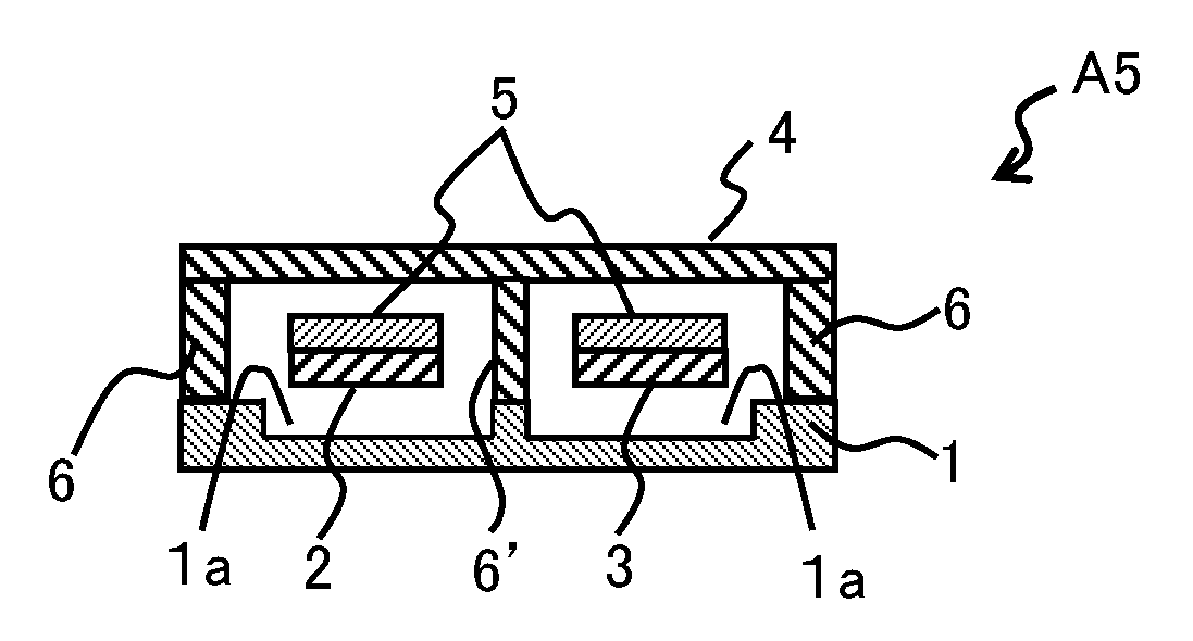
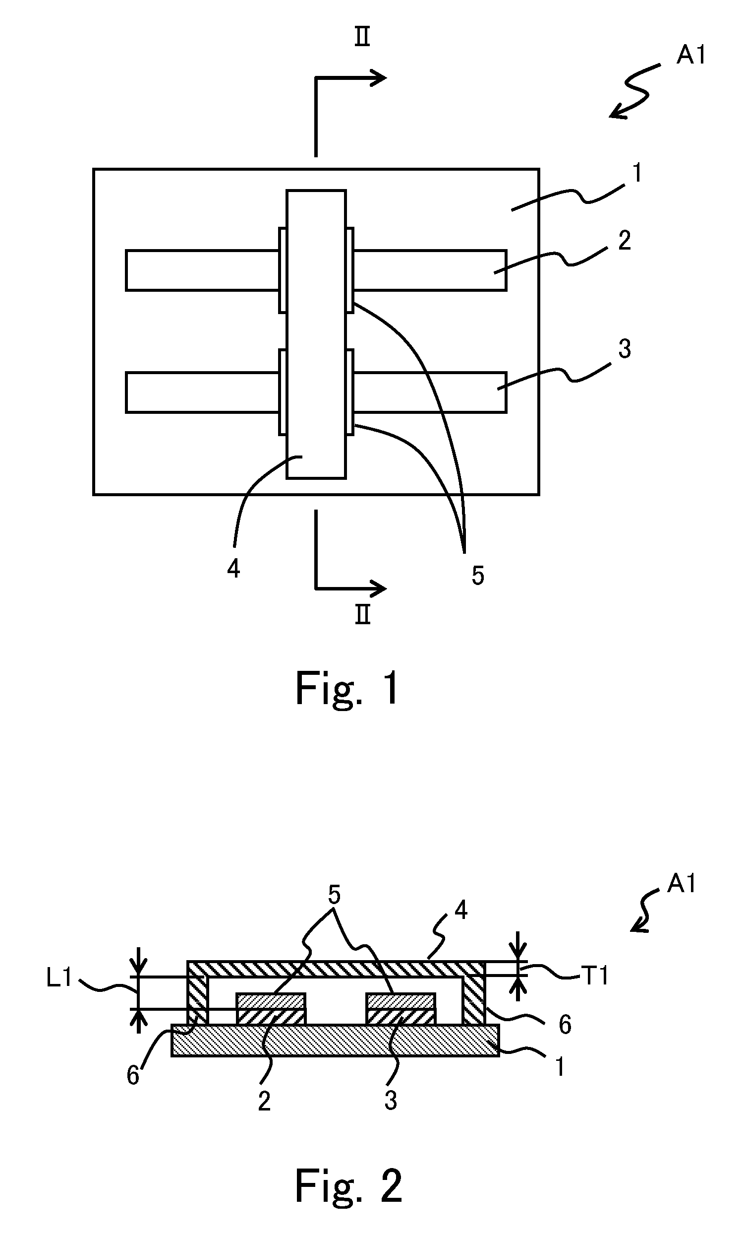
[0068]FIG. 1 and FIG. 2 are views for illustrating a variable capacitor. FIG. 1 is a plan view of the variable capacitor A1. FIG. 2 is a cross-sectional view taken along the line II-II in FIG. 1.

[0069]The variable capacitor A1 includes a substrate 1, a signal line 2, a ground electrode 3, a movable electrode 4, dielectric layers 5, and a pair of supports 6. When the variable capacitor A1 is, for example, used as a capacitive switch, the variable capacitor A1 is mounted on a printed circuit, and the signal line 2 and the ground electrode 3 are respectively connected to a signal line and ground of an electric circuit formed on the printed circuit. Note that actually the width of each dielectric layer 5 in the right-left direction in FIG. 1 is substantially equal to the width of the movable electrode 4, and the dielectric layers 5 are hidden behind the movable electrode 4 in plan view. Thus, in FIG. 1, to recognize the presence of the dielectric layers 5, the width of each dielectric l...

second embodiment

[0095]In the above described second embodiment as well, the dielectric layers 5 may also be provided on the lower face of the movable electrode 4, or may be provided only on the lower face of the movable electrode 4 instead of being provided on the both upper faces of the signal lines 2 and 2′. In addition, the dielectric layers 5 need not be provided when the variable capacitor B1 is configured so that the movable electrode 4 do not contact the signal line 2 or 2′ at an application of a maximal driving voltage. In addition, it is applicable that the dielectric layer 5 is provided for only one of the variable capacitors 11′ and 12′ (see FIG. 10) when the capacitance values of the variable capacitors 11′ and 12′ are differentiated, or the like.

[0096]Note that the shape of the signal lines 2 and 2′ is not limited to the one described in the second embodiment. If a parasitic capacitance may be ignored, the signal lines 2 and 2′ may be extended to near both ends of the substrate 1 in th...

third embodiment

[0104]In the above described third embodiment and its alternative examples as well, the dielectric layers 5 may also be provided on the lower face of the movable electrode 4′, or may be not provided on the upper faces of the signal lines 2 and 2′ but provided only on the lower face of the movable electrode 4′. In addition, when it is configured so that the movable electrode 4′ do not contact the signal line 2 or 2′ even at a maximal driving voltage, the dielectric layers 5 need not be provided. In addition, when the capacitance values of the variable capacitor 11′ and variable capacitor 12′ (see FIG. 10) are differentiated, or the like, it is applicable that the dielectric layer 5 is provided for only one of them and no dielectric layer 5 is provided for the other one.

[0105]In addition, in the variable capacitor used in series connection, the shape and arrangement of each electrode may be the same as those of the third embodiment.

[0106]FIG. 16 is a view for illustrating a fourth emb...


PUM


Abstract

There is proved a variable capacitor that includes a substrate, a signal line disposed on a surface of the substrate for feeding a signal, a ground electrode disposed on the surface, and a movable electrode opposed the signal line and the ground electrode, the movable electrode operable to move toward and away from the signal line and the ground electrode. The movable electrode can be displaced by an electrostatic attraction between the movable electrode and the signal line and between the movable electrode and the signal line. An amount of displacement of the movable electrode varies according to an amount of the voltage which generates the electrostatic attraction.

Description

CROSS-REFERENCE TO RELATED APPLICATION[0001]This application is based upon and claims the benefit of priority of the prior Japanese Patent Application No. 2008-038808, filed on Feb. 20, 2008, the entire contents of which are incorporated herein by reference.BACKGROUND OF THE INVENTION[0002]1. Field of the Invention[0003]The invention relates to a variable capacitance element (variable capacitor) and, more particularly, to a variable capacitor that is fabricated with a Micro Electro Mechanical System (MEMS) technology, a matching circuit element that uses the variable capacitor, and a mobile terminal apparatus that uses the variable capacitor or the matching circuit element.[0004]2. Description of the Related Art[0005]A variable capacitor is an important component in an electric circuit, such as a variable frequency oscillator, a tuned amplifier, a phase shifter, and an impedance matching circuit. In recent years, the number of mobile terminal apparatuses in which a variable capacito...

Claims


Application Information

Patent Timeline
Patent Type & Authority Applications(United States)
IPC IPC(8): H01G7/06
CPCH01G5/16H01L29/00
Inventor SHIMANOUCHI, TAKEAKIIMAI, MASAHIKOMI, XIAOYUUEDA, SATOSHI
Owner FUJITSU LTD
Why Eureka
Try Eureka