Check patentability & draft patents in minutes with Patsnap Eureka AI!

Methods and systems for integrated boiler feed water heating

Active Publication Date: 2009-08-27
AIR PROD & CHEM INC
View PDF13 Cites 3 Cited by
  • Summary
  • Abstract
  • Description
  • Claims
  • Application Information

AI Technical Summary

Benefits of technology

[0004]In one embodiment, a gasifier system includes a gasifier including a syngas cooler configured to transfer heat from a reaction zone of the gasifier to a flow of fluid through the syngas cooler, a reaction vessel coupled in flow communication with the syngas cooler wherein the reaction vessel is adapted to receive the flow of fluid and generate heat in an exothermic shift reaction. The system also includes a heat exchanger coupled in flow communication with the reaction v

Problems solved by technology

Pre-heating in this configuration causes the production of medium pressure and intermediate pressure steam, which has limited usefulness in other parts of the process and reduces total plant efficiency.

Method used


Image

  • Methods and systems for integrated boiler feed water heating
  • Methods and systems for integrated boiler feed water heating
  • Methods and systems for integrated boiler feed water heating

Examples


Embodiment Construction

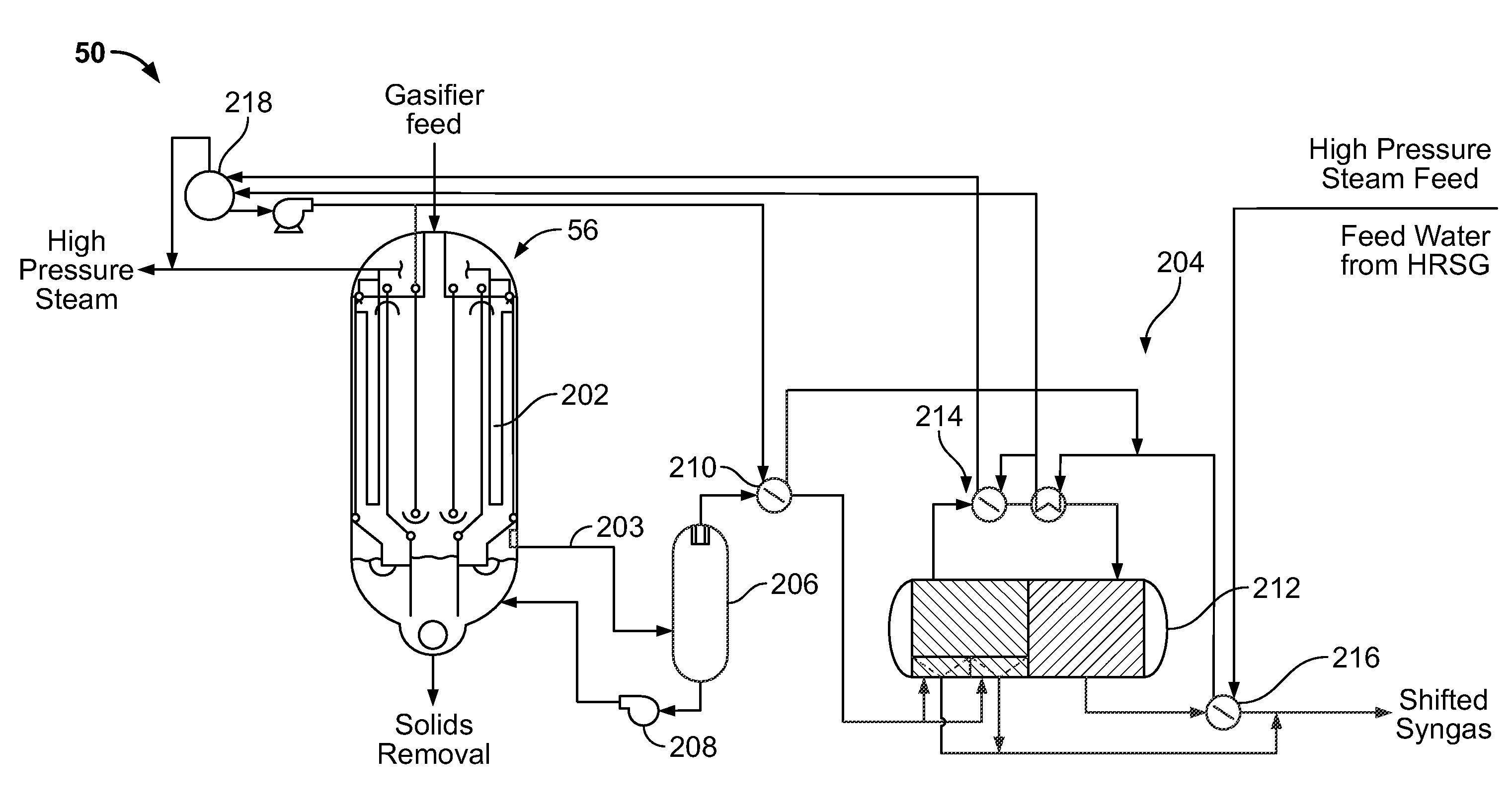
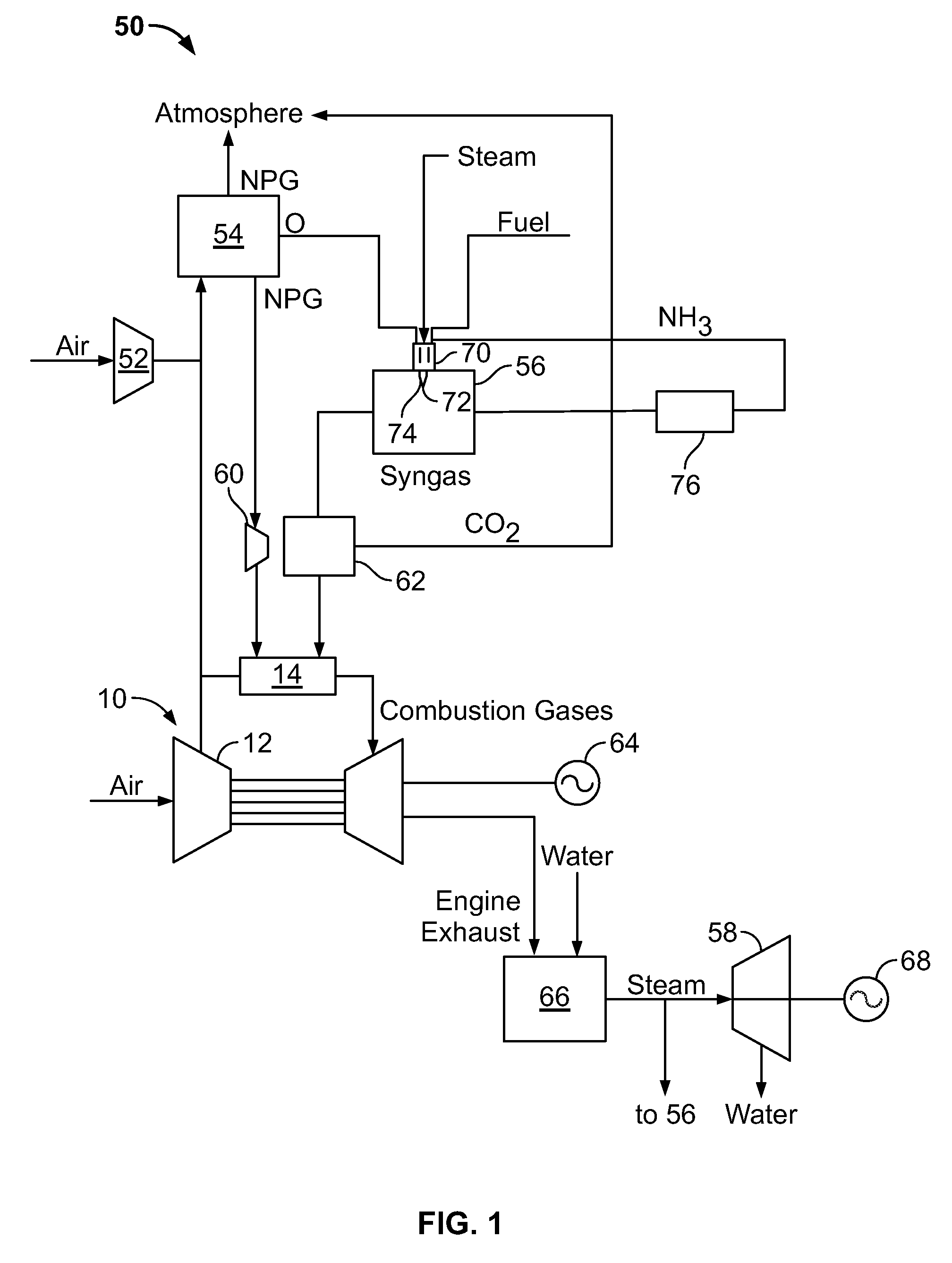
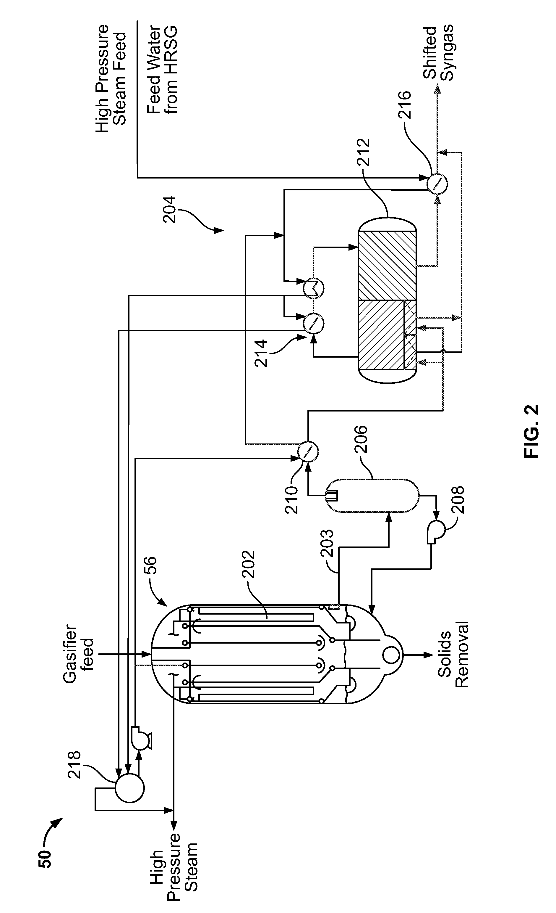
[0009]FIG. 1 is a schematic diagram of an exemplary known integrated gasification combined-cycle (IGCC) power generation system 50. IGCC system 50 generally includes a main air compressor 52, an air separation unit 54 coupled in flow communication to compressor 52, a gasifier 56 coupled in flow communication to air separation unit 54, a gas turbine engine 10, coupled in flow communication to gasifier 56, and a steam turbine 58. In operation, compressor 52 compresses ambient air. The compressed air is channeled to air separation unit 54. In some embodiments, in addition or alternative to compressor 52, compressed air from gas turbine engine compressor 12 is supplied to air separation unit 54. Air separation unit 54 uses the compressed air to generate oxygen for use by gasifier 56. More specifically, air separation unit 54 separates the compressed air into separate flows of oxygen and a gas by-product, sometimes referred to as a “process gas”. The process gas generated by air separati...


PUM


Abstract

Methods and systems for a gasifier system are provided. The gasifier system includes a gasifier including a syngas cooler configured to transfer heat from a reaction zone of the gasifier to a flow of fluid through the syngas cooler, a reaction vessel coupled in flow communication with the syngas cooler wherein the reaction vessel is adapted to receive the flow of fluid and generate heat in an exothermic shift reaction. The system also includes a heat exchanger coupled in flow communication with the reaction vessel, the heat exchanger adapted to produce relatively high pressure steam using the generated heat.

Description

BACKGROUND OF THE INVENTION[0001]This invention relates generally to integrated gasification combined-cycle (IGCC) power generation systems, and more specifically to methods and systems for optimizing heat transfer between a gasifier syngas cooler and a shift system in the IGCC system.[0002]At least some known IGCC systems include a gasification system that is integrated with at least one power producing turbine system. For example, known gasifiers convert a mixture of fuel, air or oxygen, steam, limestone, and / or other additives into an output of partially combusted gas, sometimes referred to as “syngas.” The hot combustion gases are supplied to the combustor of a gas turbine engine, which powers a generator that supplies electrical power to a power grid. Exhaust from at least some known gas turbine engines is supplied to a heat recovery steam generator that generates steam for driving a steam turbine. Power generated by the steam turbine also drives an electrical generator that pr...

Claims


Application Information

Patent Timeline
IPC IPC(8): C10J3/68C10J1/207
CPCC10J3/485C10J3/76C10J3/86C10J2300/1687Y02E20/16C10K3/04F01K23/067Y02E20/18C10J2300/1892
Inventor AVAGLIANO, AARON JOHNWALLACE, PAUL STEVEN
Owner AIR PROD & CHEM INC
Features
  • R&D
  • Intellectual Property
  • Life Sciences
  • Materials
  • Tech Scout
  • Unparalleled Data Quality
  • Higher Quality Content
  • 60% Fewer Hallucinations
Learn More