
X-ray image processing apparatus and method

Active Publication Date: 2009-08-27
CANON KK
View PDF4 Cites 6 Cited by
  • Summary
  • Abstract
  • Description
  • Claims
  • Application Information

AI Technical Summary

Benefits of technology

[0022]The present invention is directed to an X-ray moving image processing apparatus that can obtain an image with a highly diagnostic value.

Problems solved by technology

Therefore, it is extremely difficult to perform region segmentation processing without the site information.
Thus, a huge amount of calculation is needed.
In addition, results of calculation are low in precision and unstable.
However, a moving image radiographing system does not analyze an image using the site information.
Since the moving image is radiographed while a radiographing direction and a radiographing position are continuously changed, site information corresponding only to the specific site is not enough to perform an analysis of the moving image, and continuous site information is needed therefor.
Thus, an indefinitely large number of the site information is needed to analyze the moving image.
However, it is impossible to use the indefinitely large number of site information.
Accordingly, the moving image radiographing system does not perform high precision analysis and image processing using the site information.
However, the high-precision analysis using the site information is not performed for the above-described reasons.
However, according to the above-described moving image radiographing method, regardless of what subject is present at the central portion of an image, when a substance which is poor in X-ray permeability, e.g., an artificial bone is present at the central portion of the image, there are fears that necessary parts of the image may be unclearly displayed as a result of higher gradation conversion, and that excessive X-ray exposure may occur.
That is, because the moving image radiographing system cannot use important site information, only poor precision and inaccurate image processing parameters and X-ray control parameters are obtained by the simplified methods.
Accordingly, the conventional moving image radiographing method has a problem that a user thereof cannot obtain a desired radiographed image, i.e., a moving image effective for diagnosis.

Method used


Image

  • X-ray image processing apparatus and method
  • X-ray image processing apparatus and method
  • X-ray image processing apparatus and method

Examples


Embodiment Construction

[0037]Various exemplary embodiments, features, and aspects of the invention will be described in detail below with reference to the drawings.

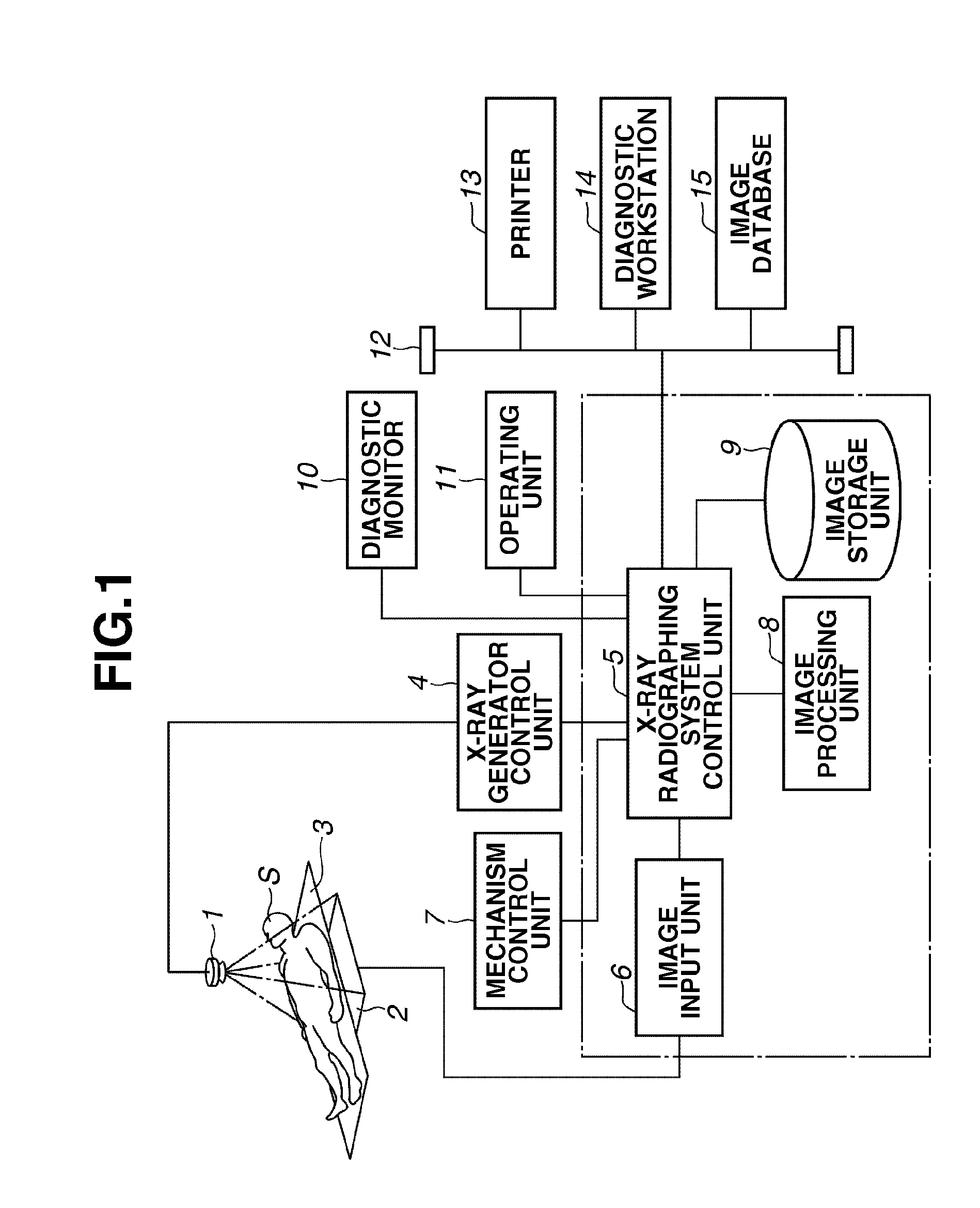
[0038]FIG. 1 illustrates a configuration of an X-ray moving image radiographing system according to an exemplary embodiment of the present invention. As illustrated in FIG. 1, an X-ray source 1 for generating X-rays and an X-ray detector 2 for detecting an X-ray generated from the X-ray source 1 are arranged to face each other. A table 3 on which a subject S is placed is arranged between the X-ray source 1 and the X-ray detector 2.

[0039]An X-ray radiographing system control unit 5 is connected to the X-ray source 1 via an X-ray generator control unit 4 for controlling generation of an X-ray. The X-ray detector 2 is connected to the X-ray radiographing system control unit 5 via an image input unit 6.

[0040]A mechanism control unit 7 for controlling a mechanism, an image processing unit 8 for performing image processing, an image storage unit 9 fo...


PUM


Abstract

An X-ray image processing apparatus includes a site information determination unit configured to determine, based on discrete site information, continuous site information to be obtained by radiographing a moving image, an information acquisition unit configured to extract, from the discrete site information, image construction information, image processing method information, and X-ray exposure control method information, a computation unit configured to compute processing information about a site located between positions represented by the discrete site information using the information extracted by the information acquisition unit, an image processing unit configured to perform image processing based on the processing information which is computed by the computation unit, and an X-ray exposure control unit configured to perform X-ray exposure based on the processing information which is computed by the computation unit.

Description

BACKGROUND OF THE INVENTION[0001]1. Field of the Invention[0002]The present invention relates to an X-ray image processing apparatus and method for performing image processing on radiographed X-ray images.[0003]2. Description of the Related Art[0004]Hitherto, an X-ray digital still image radiographing system using a flat panel detector (FPD) or a photo-stimulable phosphor determines an image processing parameter by analyzing a radiographed image. Then, image processing is performed using the image processing parameter. Thus, an optimal X-ray digital image for diagnosis is generated.[0005]FIG. 10 illustrates a chest image that can be roughly segmented into a lung field region, a mediastinal region, and direct exposure regions outside a subject. Generally, the most important part for diagnosis of the chest image is the lung field region. The chest image whose lung field region has high contrast is required. The mediastinal region of the chest image does not need to have contrast as hi...

Claims


Application Information

Patent Timeline
IPC IPC(8): G06K9/00
CPCG06T2207/10116G06T7/0012
Inventor URUSHIYA, HIROYUKI
Owner CANON KK
Learn More