Method and apparatus for detecting reverse current, and method and apparatus for driving motor

a reverse current and reverse current detection technology, applied in the direction of motor/generator/converter stopper, electronic commutator, dynamo-electric converter control, etc., can solve the problems of device breakdown, and ineffective operation of deceleration detection means, so as to avoid an increase in power supply voltage. , the effect of low vibration characteristics

Inactive Publication Date: 2009-09-03
PANASONIC CORP
View PDF15 Cites 10 Cited by
  • Summary
  • Abstract
  • Description
  • Claims
  • Application Information

AI Technical Summary

Benefits of technology

[0012]Particular embodiments provide the following advantages: the reverse flow of a phase current is detected based on various signals for the electrical conduction control to a motor coil and the voltage on the motor coil, whereby it is possible to realize a reliable phase current reverse flow detection for use in a PWM motor driving operation based on a synchronous rectification scheme. Moreover, by ...

Problems solved by technology

Moreover, the deceleration detection means may not function effectively with regeneration occurring during a motor current pull-in operation.
Therefore, if the response of the deceleration detection means is slow, it may be possible that the phase current regeneration cannot be suppressed, thereby leading to a...

Method used


Image

  • Method and apparatus for detecting reverse current, and method and apparatus for driving motor
  • Method and apparatus for detecting reverse current, and method and apparatus for driving motor
  • Method and apparatus for detecting reverse current, and method and apparatus for driving motor

Examples


Embodiment Construction

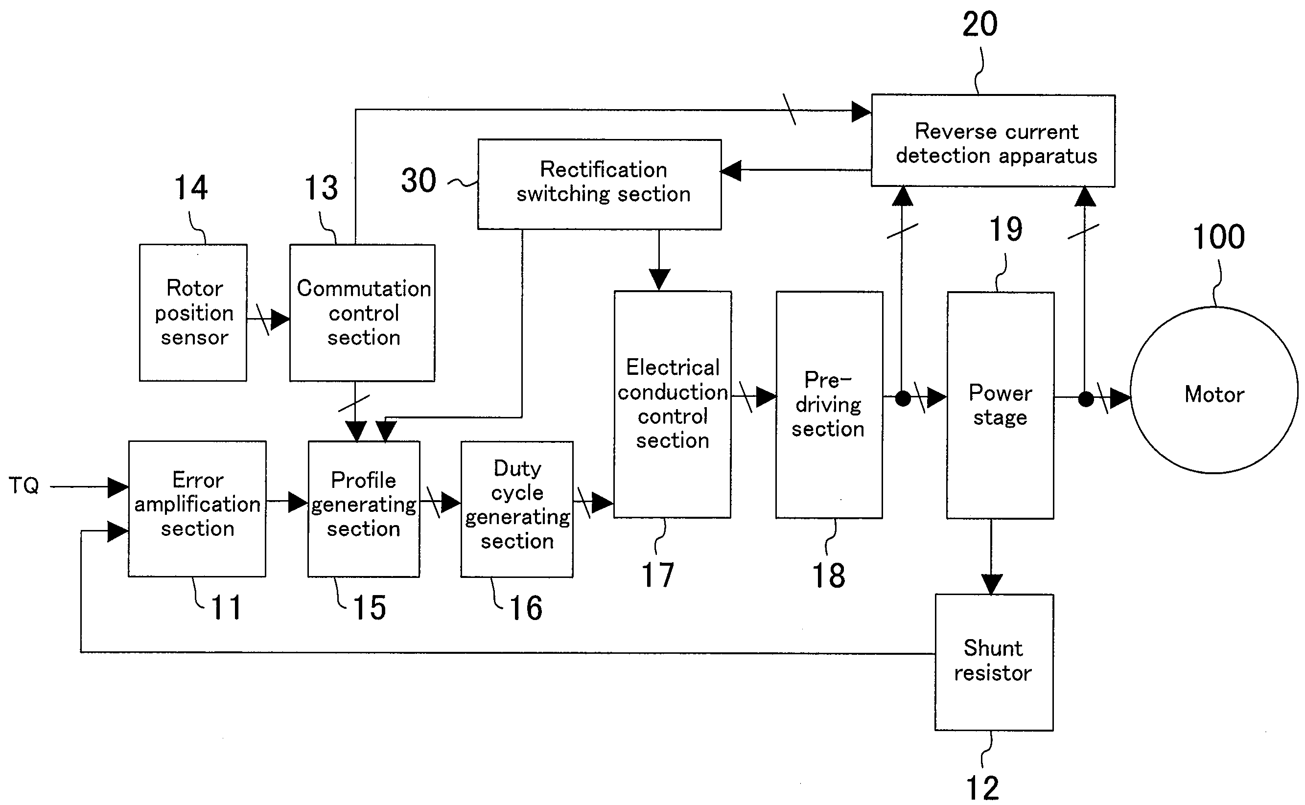
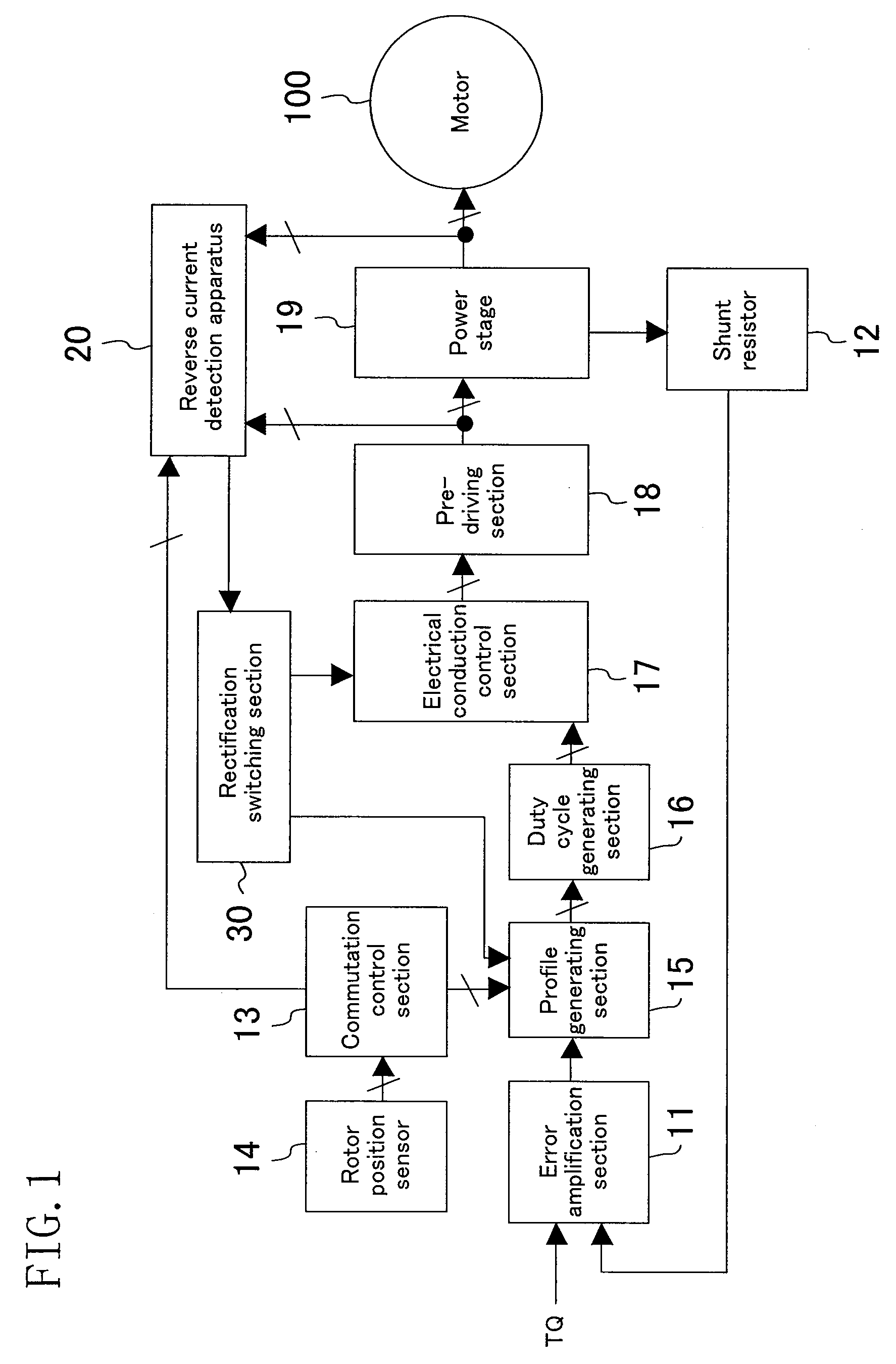
[0027]A preferred embodiment of the present invention will now be described with reference to the drawings. FIG. 1 shows a configuration of a motor driving apparatus according to an example embodiment. An error amplification section 11 amplifies the error between the torque command TQ and the voltage of a shunt resistor 12. A commutation control section 13 generates cycle information and phase information based on the output of a rotor position sensor 14. A profile generating section 15 generates a plurality of phases of voltage profiles each as an average voltage waveform to be applied to a motor 100, based on the amplified error signal, the cycle information and the phase information. A duty cycle generating section 16 generates a PWM signal based on a voltage profile. An electrical conduction control section 17 drives a pre-driving section 18 according to the PWM signal. The pre-driving section 18 performs a level conversion on the PWM signal and controls the switching of a trans...


PUM


Abstract

A reverse current detection apparatus determines whether an electrical conduction control to a motor coil of a motor is in a predetermined state based on a timing signal representing a timing at which to conduct a source current or a sink current through the motor coil and a control signal for a half bridge in a power stage, and compares the output voltage of the power stage with a threshold value, so as to detect the presence/absence of a reverse flow of a phase current based on these results. A motor driving apparatus for driving a motor under a PWM control includes a rectification switching section for switching a rectification scheme from one to another based on the reverse current detection apparatus and a detection result thereof.

Description

CROSS REFERENCE TO RELATED APPLICATION[0001]This application claims priority under 35 U.S.C. §119 on Patent Application No. 2008-51940 filed in Japan on Mar. 3, 2008, the entire contents of which are hereby incorporated by reference.BACKGROUND OF THE INVENTION[0002]The present disclosure relates to a method for driving a motor. More particularly, the present disclosure relates to detecting a reverse flow of a phase current through a PWM-driven motor, and to switching rectification schemes from one to another based on the detection.[0003]The pulse width modulation (PWM) of a synchronous rectification scheme has been widely used in the art as a motor driving method capable of reducing the power consumption. The synchronous rectification driving method has design restrictions in that some dead time needs to be provided so that at no time is there a through current caused by two transistors connected in series between the higher power supply and the lower power supply which are ON at th...

Claims


Application Information

Patent Timeline
IPC IPC(8): H02P6/14H02P6/06H02P6/08H02P6/15H02P6/16H02P6/28
CPCH02P6/14
Inventor YAMAMOTO, YASUNORINAGASE, HISANORIMORI, HIDEAKI
Owner PANASONIC CORP
Why Eureka
Try Eureka