Method and system for tunable pulsed laser source

a laser source and pulse technology, applied in semiconductor lasers, laser details, optical resonator shape and construction, etc., can solve the problems of difficult to achieve a range of variable pulse characteristics and compromising laser performance, so as to maximize energy extraction efficiency in the laser system, optimize the pulse profile, and maintain pulse-to-pulse stability

Inactive Publication Date: 2009-09-03
ELECTRO SCI IND INC
View PDF12 Cites 34 Cited by
  • Summary
  • Abstract
  • Description
  • Claims
  • Application Information

AI Technical Summary

Benefits of technology

[0018]Numerous benefits are achieved using the present invention over conventional techniques. For example, in an embodiment according to the present invention, high power, pulsed lasers suitable for laser processing are provided that utilize a compact architecture that is inexpensive in comparison to lasers with comparable performance characteristics. Moreover, in embodiments of the present invention, short pulses are generated with pulse characteristics that are tunable in real-time while maintaining pulse-to-pulse stability. Furthermore, in an embodiment according to the present invention, optical pulses can be shaped to optimize the pulse profile for the particular application, or to maximize energy extraction efficiency in the laser system. In a particular embodiment according to the present invention, drifting of transmitted light signals can be reduced by including a tap coupler and a photo-detector to detect a portion of transmitted signals through an amplitude modulator and applying a DC bias to the amplitude modulator. The DC bias depends on an output s

Problems solved by technology

However, such lasers produce optical pulses with characteristics that are predetermined by the cavity geometry, the mirror reflectivities, and the like and cannot gener

Method used


Image

  • Method and system for tunable pulsed laser source
  • Method and system for tunable pulsed laser source
  • Method and system for tunable pulsed laser source

Examples


Embodiment Construction

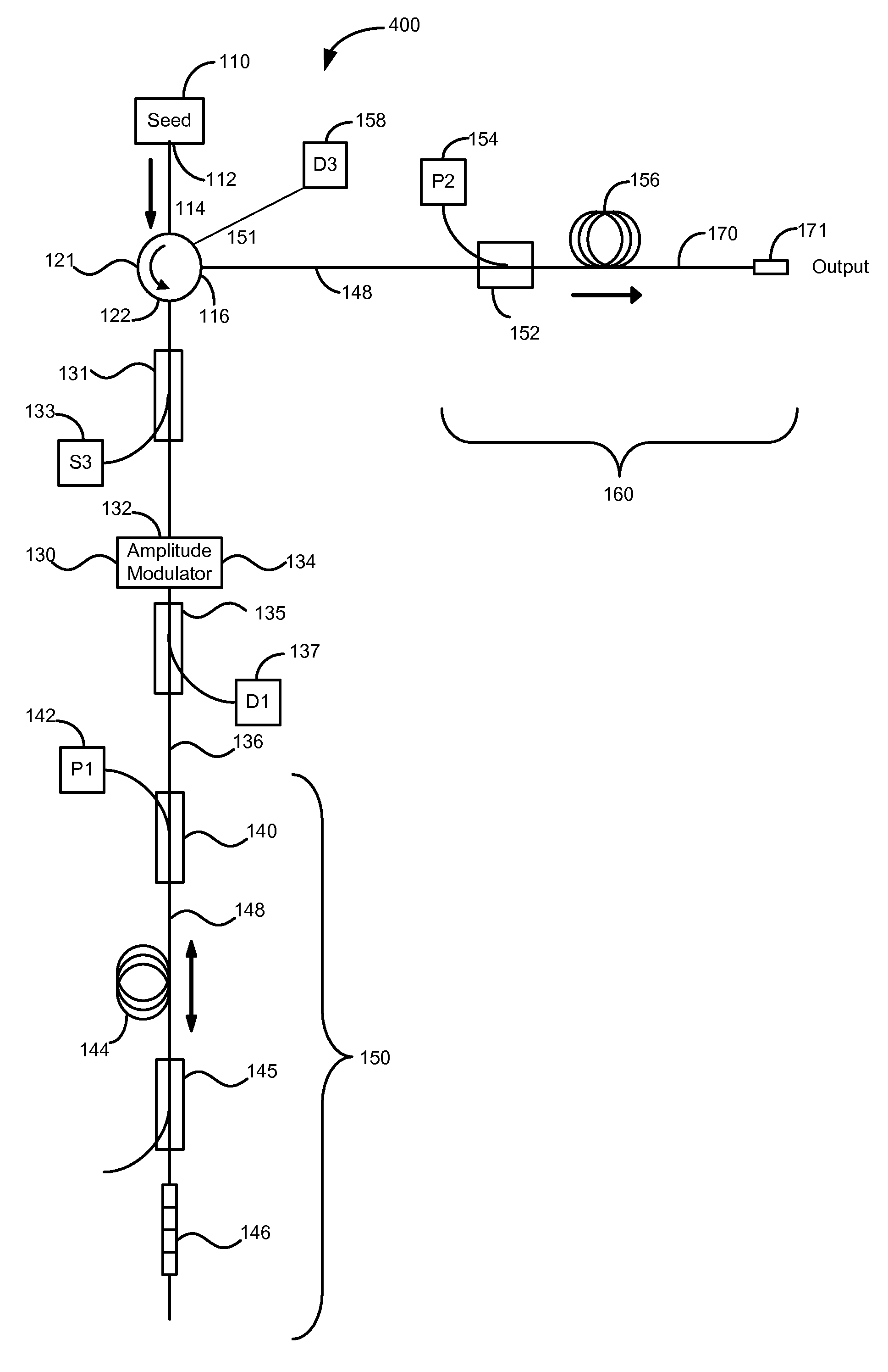
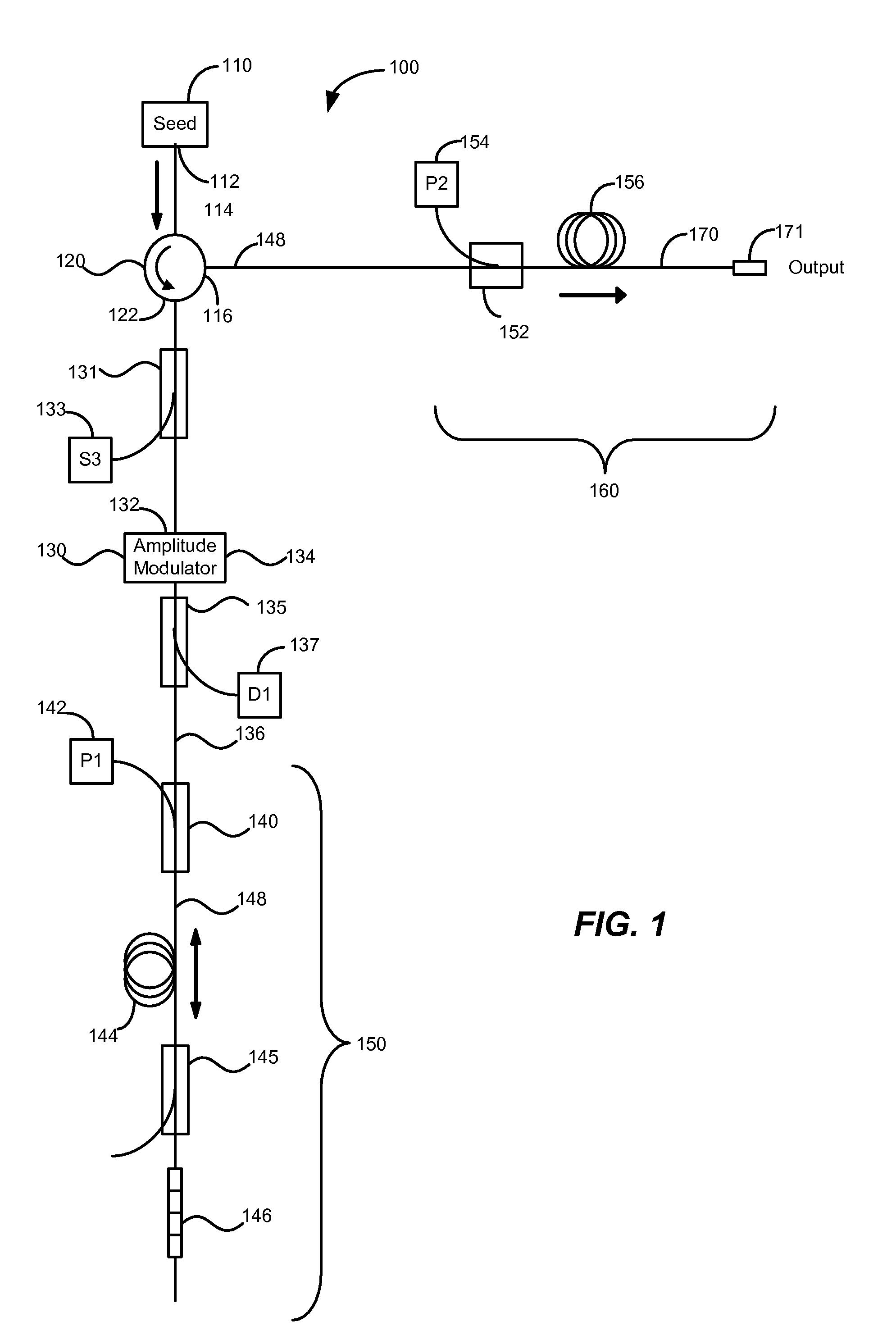
[0030]FIG. 1 is a simplified schematic illustration of a high power pulsed laser with tunable pulse characteristics using optical fiber amplifiers according to an embodiment of the present invention. High power pulsed laser 100 includes a seed source 110 that generates a seed signal that is injected into a first port 114 of an optical circulator 120. Circulators are well known in the art and are available from several suppliers, for example, model OC-3-1064-PM from OFR, Inc. of Caldwell, N.J. According to an embodiment of the present invention, the optical seed signal is generated by using a seed source 110 that is a continuous wave (CW) semiconductor laser. In a particular embodiment, the CW semiconductor laser is a fiber Bragg grating (FBG) stabilized semiconductor diode laser operating at a wavelength of 1064 nm with an output power of 150 mW. In other embodiments, the seed source 110 operates at a wavelength around 1550 nm. The power can be lower or greater than 150 mW. For exam...


PUM


Abstract

A tunable pulsed laser includes a seed source and an optical circulator. The optical circulator includes at least a first port coupled to the seed source, a second port, and a third port. The laser also includes an amplitude modulator characterized by a first optical side and a second optical side. The first optical side is coupled to the second port of the optical circulator. The laser further includes a first optical amplifier characterized by an input end and a reflective end. The input end is optically coupled to the second side of the amplitude modulator. The laser additionally includes a tap coupler optically coupled to the amplitude modulator and characterized by a pre-determined split ratio. Moreover, the laser includes a first photo-detector optically coupled to the tap coupler and adapted to receive a portion of the seed signal transmitted through the amplitude modulator and to generate an output signal.

Description

CROSS-REFERENCES TO RELATED APPLICATIONS[0001]This application claims priority to U.S. Provisional Patent Application No. 61 / 021,453, filed on Jan. 16, 2008, and entitled “METHOD AND SYSTEM FOR TUNABLE PULSED LASER SOURCE,” the disclosure of which is hereby incorporated by reference in its entirety for all purposes.BACKGROUND OF THE INVENTION[0002]The present invention relates generally to the field of tunable laser sources. More particularly, the present invention relates to a method and apparatus for providing high power pulsed laser sources useful for industrial applications such as trimming, marking, cutting, and welding. Merely by way of example, the invention has been applied to a laser source with real-time tunable characteristics including pulse width, peak power, repetition rate, and pulse shape. However, the present invention has broader applicability and can be applied to other laser sources.[0003]Pulsed laser sources, such as Nd:YAG lasers have been used to perform laser...

Claims


Application Information

Patent Timeline
IPC IPC(8): H01S3/10
CPCH01S3/06712H01S3/06754H01S3/10015H01S2301/02H01S3/1618H01S3/2333H01S3/10084
Inventor MURISON, RICHARDPANARELLO, TULLIOREID, BENOITBOULA-PICARD, REYNALDCAPLETTE, STEPHANE
Owner ELECTRO SCI IND INC
Why Eureka
Try Eureka