[0009]The invention solves the above problems by providing a novel miniature biocompatible electro-acoustic
transducer apparatus. The apparatus includes a vibrating element utilizing a
piezoelectric membrane element installed within a sealed case wherein one end of the piezoelectric element is in static positioned relationship with respect to its casing (i.e., it is connected to the case) and the other end is free to move and to vibrate. As will be apparent to the skilled person, the case has to be resistant to its environment, such as to
saliva and foodstuff that may come in contact with it. Preferably, the
center of mass of the piezoelectric element is closer to its free end than to its fixed end (e.g., the free moving end carries a weight element). The apparatus is small enough to be placed in hearing aids, such as those described in U.S. Pat. No. 5,447,489, and enables efficient sound transfer simply by establishing contact with a vibration-propagating part of the body or
prosthesis (a
human bone, teeth, or prosthetic element).
[0010]Preferably, the piezoelectric
transducer element (i.e., that membrane) is configured so as to on the one hand increase the load applied to the contacting element of the body (e.g., tooth) at a given amplitude of vibrations (and thereby increase the output), and on the other hand optimize the natural vibration frequency of the
transducer, namely so as to be in the lower part of a hearing frequency range. According to a preferred embodiment of the invention, this is achieved by configuring the transducer element so as to have, in a region thereof at its free moving section, an increased weight as compared to other regions of the transducer element. This may be implemented by appropriately patterning the transducer element to have a specific thickness and / or
material distribution (varying relief), or by placing a weight element or load on the free moving section of the transducer.
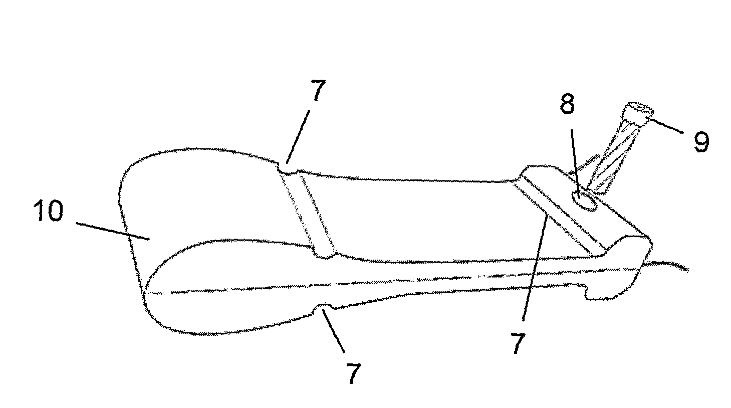
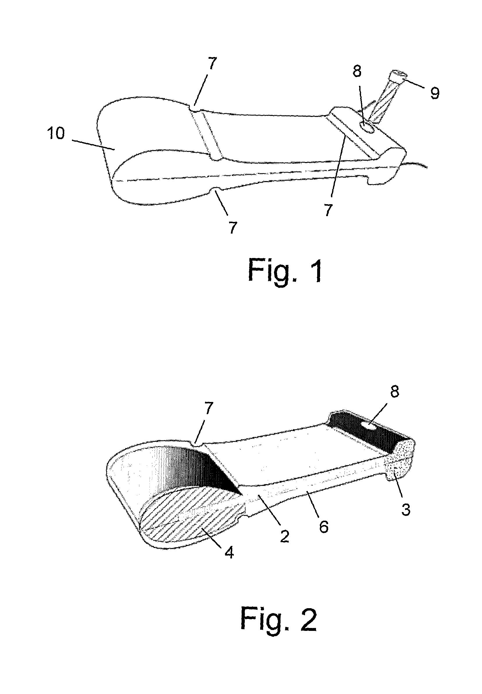
[0011]According to one preferred embodiment of the invention the transducer has a substantially rectangular geometry, but as will be apparent to the skilled person, it may have any suitable different geometry, such as triangular, trapezoidal, or circular configuration with the larger-dimension edge being the free moving one. The transducer is enclosed in a sealed case configured for mounting on a patient's body and in contact with a bone, tooth, or prosthetic element. It should be noted that the weight element may be any load. It may be convenient to use as a weight element the
electronics typically required for the hearing device operation, as this may save space, but of course any other suitable type of weight element can be employed.
[0013]It should also be noted that the term “free moving” or “
free movement” used herein signifies a movement with or without suitable
damper means. The device may be configured as a sealed box (case) made of bio-compatible materials incorporating a dedicated vibrating unit, which includes a
ceramic piezoelectric membrane element, a
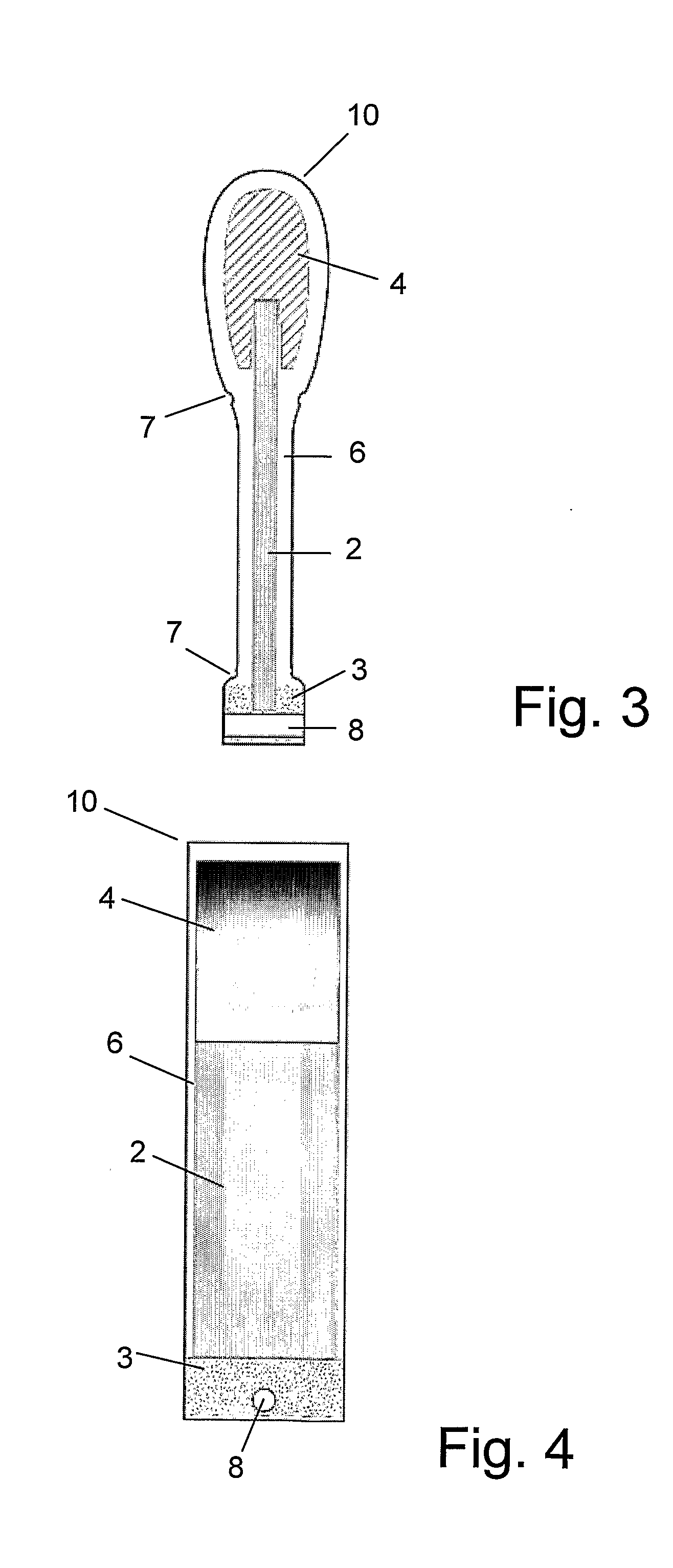
fastener for attaching the membrane element to the box at its one end, thereby leaving the other (e.g., heavier-weight) end of the membrane element free for movement (vibration). The apparatus operates with high performance when positioned against the palatal bone, a tooth, or an
implant, either by a simple contact, or when attached by hooks, screws, glue or any other means. The size of the apparatus is small enough to be incorporated in hearing aids, in particular of the type that is positioned within a patient's mouth, and typically (but not limitatively), not larger than 20 mm, 10 mm, and 5 mm in correspondingly length, height and width dimensions.
[0015]According to another preferred embodiment of the present invention, there is provided a vibrating element for use in a transducer apparatus of a hearing device, the vibrating element comprising: an elongated piezoelectric membrane element configured to have a
weight distribution such as to have the highest weight close to its end, and fastening means configured for fixing in place the other end of the piezoelectric membrane element and leaving said one heaviest-weight end thereof free for vibration.

